Method and system for long haul optical transport for applications sensitive to data flow interruption

Inactive Publication Date: 2010-11-23
AMERICAN TELEPHONE & TELEGRAPH CO
View PDF8 Cites 24 Cited by
  • Summary
  • Abstract
  • Description
  • Claims
  • Application Information

AI Technical Summary

Benefits of technology

[0016]The present invention is intended to provide a method and system by which a high level of network availability is provided to an optical network. These objectives are achieved by employing the use of optical network elements to allow the substantially simultaneous broadcast of data through a plurality of diverse network paths and network elements. The system utilizes network elements to conduct the following steps: assigning four (4) wavelength channels to each data channel; broadcasting the same data on each of th

Problems solved by technology

Today, even applications such as e-mail have become critical for ongoing business operations.
Any downtime during mission critical applications can severely impact business operations and cost valuable time, money, and resources.
One of the challenges of building an optical network is building in these availability objectives and characteristics, given the long spans of optical fiber used for example in long haul networks.
Despite these redundancy measures, and monitoring techniques used, there is no escaping the reality that the frequency of switch to protect events increases with increasing transport distance.
However, these protection switches, though infrequent, involve a small, predictable but very real brief loss of data transmission continuity.
In more recent data applications such as high speed optical networks used with mission-critical applications, these brief, infrequent protection switching events may bring about a halt in the application and possibly require lengthy data resynchronization activity before the application is restarted.
Although connectionless packet transport networks are less sensitive to brief interruptions in transport continuity due to sophisticated routing mechanisms, they remain a source for network failure.
Connectionless transport can potentially have large, unavoidable variations in latency.
For high volume networks, any downtime may mean the loss

Method used


Image

  • Method and system for long haul optical transport for applications sensitive to data flow interruption
  • Method and system for long haul optical transport for applications sensitive to data flow interruption
  • Method and system for long haul optical transport for applications sensitive to data flow interruption

Examples


Example

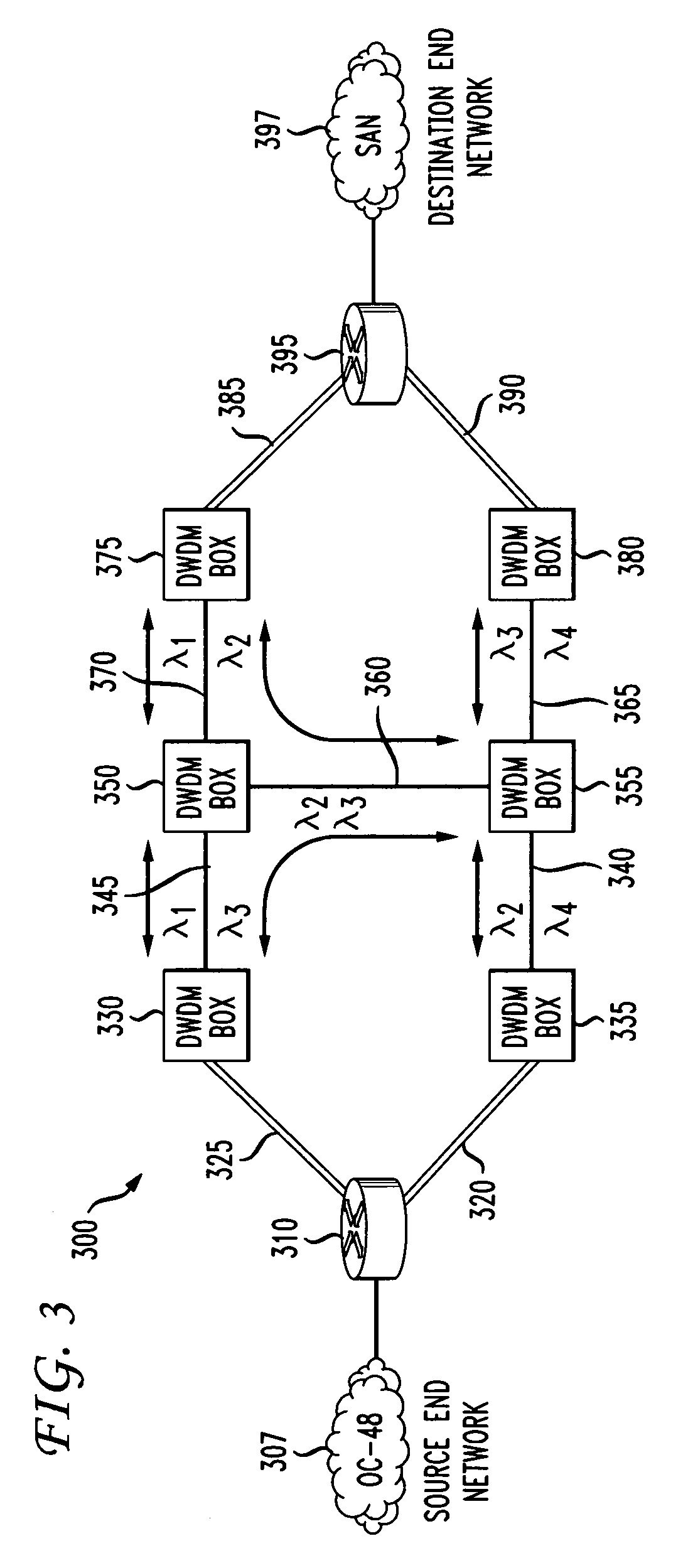
[0027]Shown in FIG. 3 is an optical network 300 functioning as a high speed transport of data from an optical source end network 307 (for example an OC-48) source to a destination end network 397 (for example a San) and using at least two (2) diversely routed DWDM (Dense Wavelength Division Multiplex(ed)(er)) circuits with end and intermediate DWDM equipment boxes 330, 335, 375, 380350, 355 spaced within the route mileage that corresponds to an expected level of network availability. These intermediate DWDM boxes 350, 355 are connected with optical fiber 360 transverse to the two (2) main optical spans (links 345, 370 and 340, 365). Switch 310 receives and transmits data from various source side network elements preferably in optical form. If necessary electrical data may be optically converted in switch 310. Also the switch may have other on board electrical signals. Switch 310 may take the form of a router, Ethernet switch, or SAN (Storage Area Network) switch or any other network...


PUM


Abstract

An optical network broadcasts the same data on a plurality of wavelength channels from a source network to destination network. The network elements of the optical network are configured so as to provide four diversely routed transmission pathways. At the receiving end, one of the plurality of wavelength channels is selected as the primary wavelength channel.

Description

FIELD OF THE INVENTION[0001]The present invention relates to a method and system for enhancing network availability. Network failures within an optical network are protected against disruption by provisioning a multitude of alternate optical paths without need for protection switches.BACKGROUND OF THE INVENTION[0002]Businesses are becoming increasingly reliant on computer networks for mission critical applications. With the emergence of the Internet and the proliferation of global e-business applications, more and more organizations are implementing computing infrastructures specifically designed for reliably accessible data and system availability. Today, even applications such as e-mail have become critical for ongoing business operations.[0003]Faced with increased customer and internal user expectations, organizations are currently striving to achieve the highest availability in their computing systems. Any downtime during mission critical applications can severely impact busines...

Claims


Application Information

Patent Timeline
IPC IPC(8): G01R31/08H04B10/08
CPCH04J14/0227H04J14/0294H04Q11/0062H04J14/0206H04J14/021H04J14/0212H04Q2011/0081H04Q2011/0084
Inventor GARDNER, JAMES A.
Owner AMERICAN TELEPHONE & TELEGRAPH CO
Why Eureka
Try Eureka