Temperature controller for small fluid samples with different heat capacities

a temperature controller and fluid sample technology, applied in the field of temperature control devices, can solve the problems of inability to meet the requirements of rapid temperature changes, inability to provide rapid temperature changes, and inability to accurately and uniformly adjust the temperature of the temperature controller

Inactive Publication Date: 2010-11-30
OSCILLOGY LLC
View PDF20 Cites 1 Cited by
  • Summary
  • Abstract
  • Description
  • Claims
  • Application Information

AI Technical Summary

Problems solved by technology

In addition to the requirement to maintain multiple samples at the same constant temperature for a period of time, it is sometimes desirable also to change the analysis temperature rapidly between sets of samples.
In the design of temperature controllers, these competing requirements often conflict.
In particular, controllers that are capable of precise and uniform temperature regulation over time and amongst samples are generally not also adept at rapid temperature changes.
Conversely, temperature controllers that can provide rapid temperature changes are often not precise and uniform.
First, if the samples have widely varying thermal characteristics, their temperatures will not always be uniform, because local variations within the block are not monitored or independently regulated.
Second, the thermal mass of the block is usually substantially larger than the thermal mass of small liquid samples.
The large thermal mass of the block makes it difficult to change sample temperature rapidly.
For very small fluid samples, it introduces the complexity of measuring temperature in a very small sample.
Temperature sensors amenable to miniaturization, such as thermocouples, do not provide accuracy comparable to larger sensors, such as thermistors.
Also, it is often impractical to measure the fluid sample temperature directly, and a surrogate temperature (for example temperature on the surface of a capillary where the capillary contains the sample) is measured instead (Friedman N A, Meldrum D R. Capillary tube resistive thermal cycling.
However, without the essentially isothermal temperature field provided by a conductive block, this can lead to errors in sample temperature measurement.
As a result, individually controlling the temperatures of small fluid samples allows rapid changes in temperature, but does not usually result in the precision or uniformity (over time and between samples) of temperature control that is provided by a conductive block.
Certain kinds of applications, in particular the MIGET by MMIMS analysis, therefore present multiple performance requirements that are not completely satisfied by prior art.
While prior art presents designs that meet these performance requirements individually, there is no prior art approach that meets all of these performance requirements.
U.S. Pat. No. 6,730,883 teaches that earlier heater assemblies for carrying out PCR in discrete (i.e. non-flowing) samples in sample tubes did not provide uniform thermal contact with each sample tube cap, resulting in non-uniformity of temperature control between the samples, resulting in less efficiency of the PCR reactions.
The thermal heating block teaches the use of various heater elements such as thermoelectric and resistive, and heat sinks such as forced convection and thermoelectric, but does not teach limitation of the samples to essentially a single plane positioned between a heat source and heat sink.
The device also does not discuss the use of channels for flowing samples through the heater block.
U.S. Pat. No. 6,703,236 also teaches that in earlier thermal conductive blocks for discrete samples for the PCR reaction, non-uniformity of temperatures between samples was a problem that led to less efficiency.

Method used


Image

  • Temperature controller for small fluid samples with different heat capacities
  • Temperature controller for small fluid samples with different heat capacities
  • Temperature controller for small fluid samples with different heat capacities

Examples


Embodiment Construction

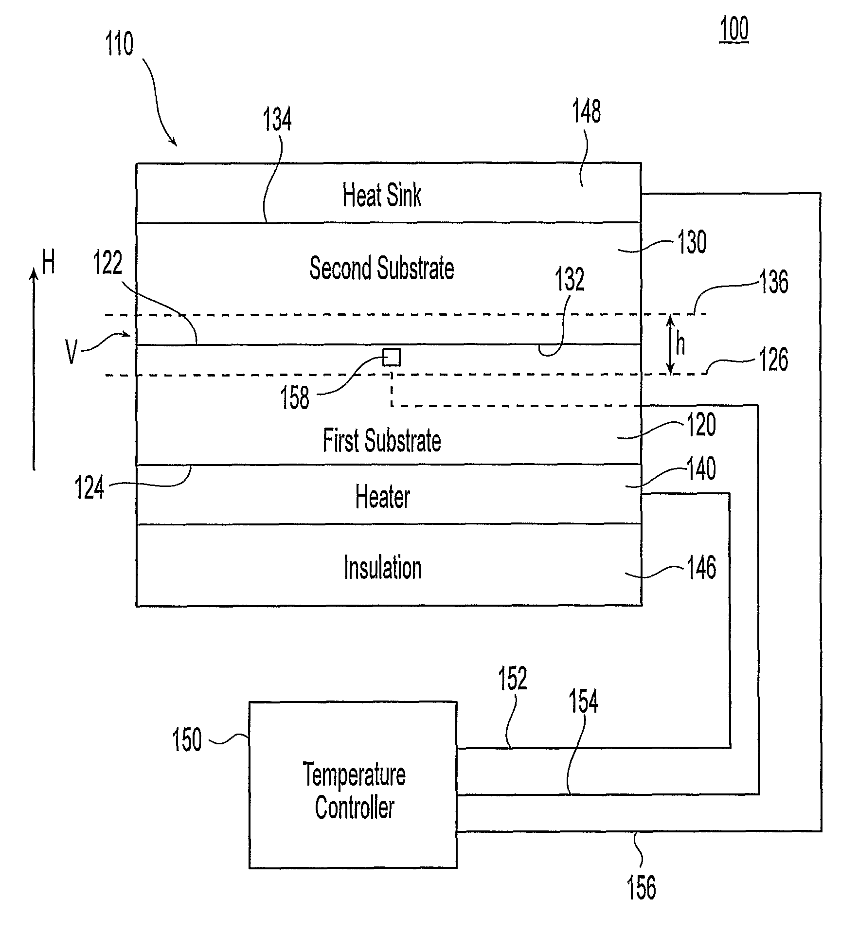
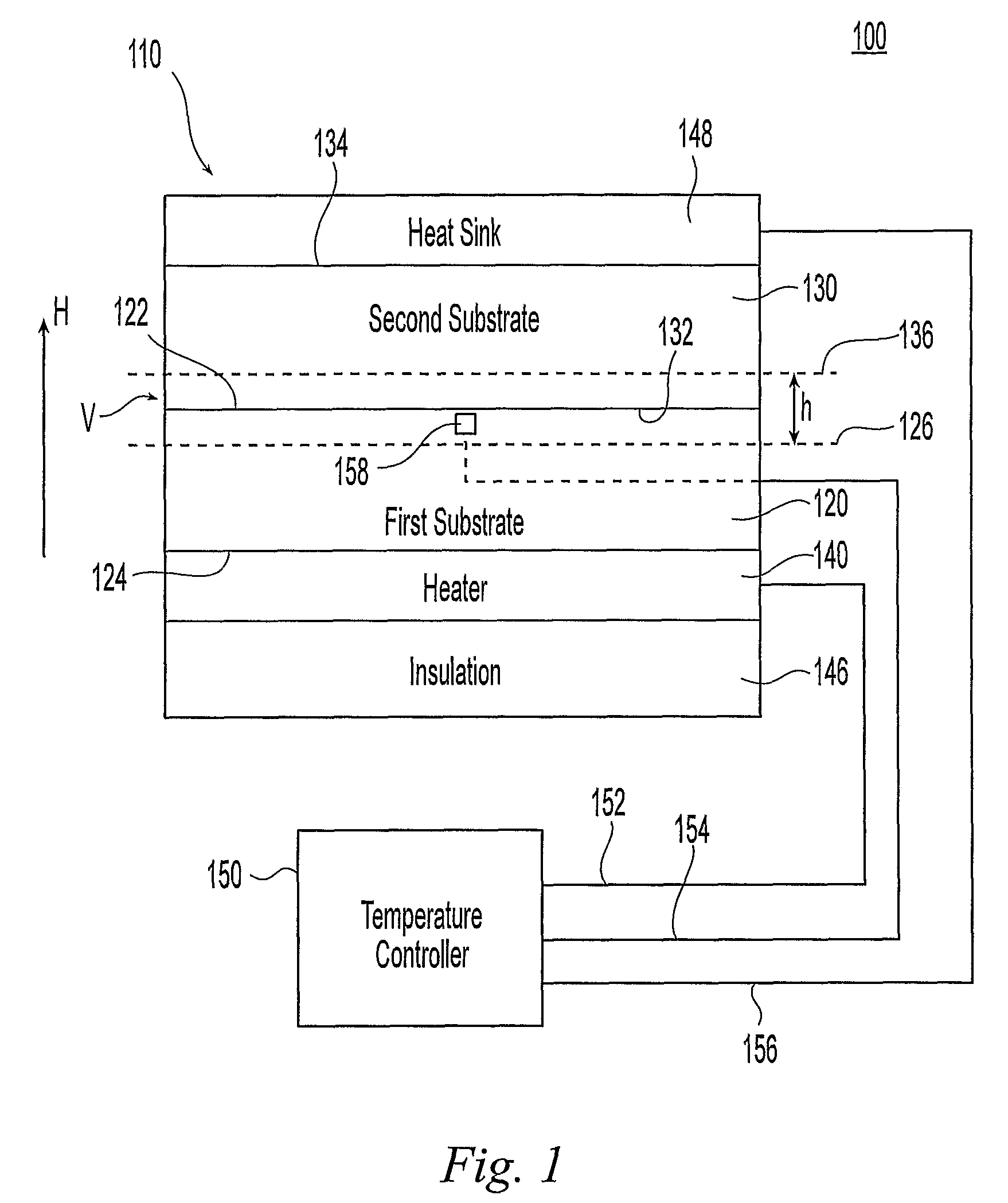
[0035]FIG. 1 shows an embodiment of a system 100 in accordance with the present invention. The system includes a fluidic chip assembly 110 and a temperature controller 150. The fluidic chip assembly 110 includes a first substrate block 120 and a second substrate block 130. The first substrate block 120 has a first inner surface 122 and first outer surface 124, while the second substrate block 130 has a second inner surface 132 and second outer surface 134. The first and second substrate blocks 120, 130 are such that, in the assembled state and during use, the first inner surfaces 122, 132 oppose, or face, each other and, more preferably, abut one another. Also, the first and second substrate blocks 120, 130 are such that, in the assembled state and during use, the first and second outer surfaces 124, 134, preferably are planar and parallel to one another.

[0036]As is known to those skilled in the art, the first and second substrate blocks typically are separately formed, one or both ...


PUM

PropertyMeasurementUnit
temperatureaaaaaaaaaa

Abstract

A system for controlling the temperature of fluidic samples includes a device having a first outer surface and a second outer surface which are parallel to one another. The interior of the device contains two or more channels suitable for accommodating samples. The channels lay on a common plane that is also parallel to the first and second outer surfaces. A temperature sensor is positioned between the channels along the common plane. A heater is thermally coupled to one of the two outer surfaces while a heat sink is coupled to the other of the two outer surfaces, thereby establishing a temperature gradient between the first and second outer surfaces. A temperature controller receives sensed temperature input from the temperature sensor and adjusts the heater in response thereto.

Description

RELATED APPLICATIONS[0001]The present application claims priority to U.S. Provisional Application No. 60 / 646,514, filed Jan. 25, 2005. The contents of the aforementioned provisional application are incorporated by reference in their entirety.FIELD OF THE INVENTION[0002]The present invention relates to temperature control devices used to maintain a temperature of fluidic samples. More particularly, it concerns such devices that are suitable for samples having different heat capacities.BACKGROUND OF THE INVENTION[0003]Certain kinds of analytic procedures require the analysis of multiple fluid samples, where the samples have markedly different thermal characteristics, for example different heat capacities. A specific example is the MIGET by MMIMS (Multiple Inert Gas Elimination Technique by Micropore Membrane Inlet Mass Spectrometry) analysis, in which inert gas partial pressures are measured in two blood samples and one gas sample (Baumgardner J E, Choi I-C, Vonk-Noordegraaf A, Frasch...

Claims


Application Information

Patent Timeline
Patent Type & Authority Patents(United States)
IPC IPC(8): G01N1/22B01L99/00
CPCB01L3/5027B01L3/502715B01L7/54B01L5/00B01L2200/147B01L2300/1822B01L2300/1827B01L2300/1844B01L2300/185
Inventor BAUMGARDNER, JAMES E.
Owner OSCILLOGY LLC
Why Eureka
Try Eureka