Treatment device, treatment device consumable parts management method, treatment system, and treatment system consumable parts management method

a technology of consumable parts and management methods, applied in the direction of fluid pressure measurement, process and machine control, instruments, etc., can solve the problems of consumable component wear extent change rate in correspondence, consumable component wear extent can be accurately estimated, and the rate at which consumable components become worn under given processing conditions is different from the rate at which they become worn under different processing conditions

Inactive Publication Date: 2010-11-30
TOKYO ELECTRON LTD
View PDF6 Cites 6 Cited by
  • Summary
  • Abstract
  • Description
  • Claims
  • Application Information

AI Technical Summary

Benefits of technology

[0011]An object of the present invention, having been completed by addressing the issues of the related art discussed above, is to provide a processing apparatus, a consumable component management method to be adopted in a processing apparatus, a processing system and a consumable component management method to be adopted in a processing system, with which extents of wear of consumable components can be estimated accurately and the optimal timing for consumable component replacement can be indicated even when a plurality of types of processing are executed under different processing conditions and execution ratios of the various types of processing do not remain constant.
[0014]According to the present invention disclosing the apparatus and the method described above, the wear index is calculated for the consumable component based upon the utilization statuses corresponding to the various types of processing and the wear coefficients corresponding to the various types of processing and thus, the consumable component wear index thus calculated reflects the execution ratios of the various types of processing. As a result, even when various types of processing are executed under different processing conditions inside the processing chamber and the execution ratios of the individual types of processing do not remain constant, the extent to which the consumable component becomes worn can be estimated accurately and the optimal consumable component replacement timing can be indicated. Consequently, the consumable component replacement instruction is issued in a timely manner before the consumable component becomes worn to an extent at which processing target substrate processing characteristics are adversely affected. At the same time, the optimal consumable component management is assured, since the consumable component replacement instruction is never issued prematurely before the consumable component actually becomes worn to an extent requiring replacement.
[0019]Since the consumable component replacement timing and the information on the consumable component to be replaced are displayed at the display means, the operator is able to ascertain with ease the exact consumable component that needs to be replaced. As a result, the efficiency of consumable component replacement is improved. In addition, when there are a plurality of consumable components that need to be replaced, a combination of consumable components that can be replaced all at once is indicated so as to further improve the efficiency of the consumable component replacement.
[0024]According to the present invention disclosing the system and the method described above, the wear index is calculated for the consumable component based upon the utilization statuses corresponding to the various types of processing and the wear coefficients corresponding to the various types of processing and thus, the consumable component wear index thus calculated reflects the execution ratios of the various types of processing. As a result, even when various types of processing are executed under different processing conditions inside the processing chamber and the execution ratios of the individual types of processing do not remain constant, the extent to which the consumable component becomes worn can be estimated accurately and the optimal consumable component replacement timing can be indicated. In addition, the wear coefficient information for the consumable components is obtained from the external apparatus and thus, the processing apparatus does not need to store the wear coefficient information. As a result, the onus placed on the processing apparatus is reduced.
[0028]The processing for indicating the consumable component replacement timing may include processing through which information indicating the consumable component replacement timing and information on the consumable component for which the replacement timing is indicated are displayed at a display means and processing through which information indicating a candidate a consumable component selected to be used as a consumable component replacement based upon a preset selection criterion is obtained from the external apparatus and the candidate consumable component information is displayed at the display means. The processing may instead include processing through which replacement procedure information indicating a procedure to be followed when replacing the consumable component with a replacement is obtained from the external apparatus and the replacement procedure information is displayed at the display means. Through the processing described above, the correct candidate consumable component can be selected and the replacement routine can be performed with ease even by an operator without expert knowledge on consumable component replacement operation.
[0030]According to the present invention, the wear extent of a consumable component can be accurately estimated and the optimal consumable component replacement timing can be indicated even when a plurality of types of processing are executed under different processing conditions and the execution ratios of the various types of processing do not remain constant.

Problems solved by technology

However, the rate at which the consumable components become worn under given processing conditions is different from the rate at which they become worn under different processing conditions.
Thus, there arises a concern that when a plurality of types of processing are executed under varying processing conditions in a single processing chamber, the consumable component wear extent change rate changes in correspondence to the ratio at which the various types of processing are executed.
As a result, a consumable component may become totally worn earlier than estimated before a consumable component replacement instruction is issued.
In such a case, the processing characteristics with which processing target substrates are processed will be adversely affected.

Method used


Image

  • Treatment device, treatment device consumable parts management method, treatment system, and treatment system consumable parts management method
  • Treatment device, treatment device consumable parts management method, treatment system, and treatment system consumable parts management method
  • Treatment device, treatment device consumable parts management method, treatment system, and treatment system consumable parts management method

Examples


first embodiment

(Substrate Processing Apparatus Achieved in the First Embodiment)

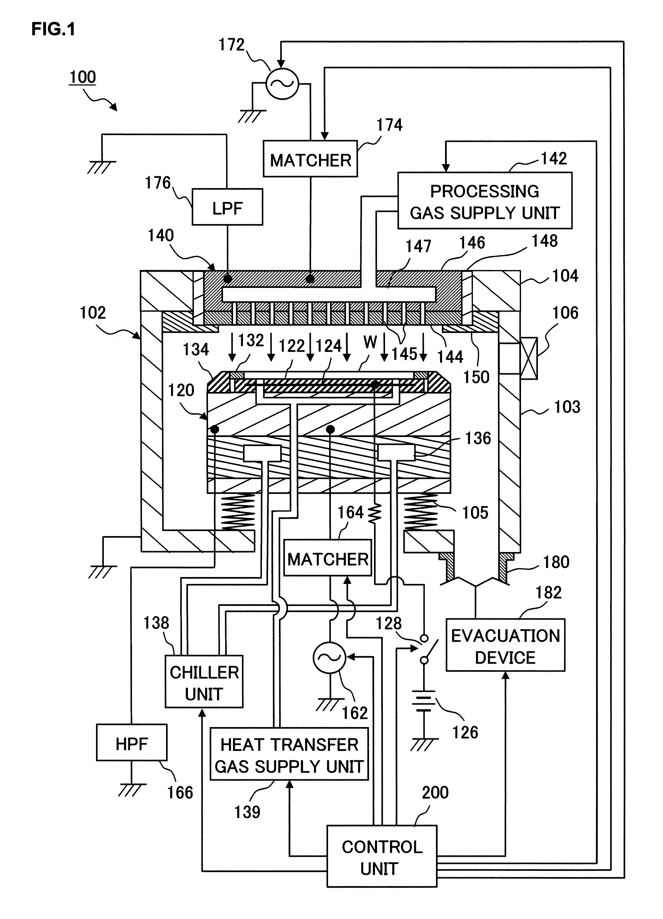
[0110]First, the first embodiment achieved by adopting the processing apparatus according to the present invention in a substrate processing apparatus that processes processing target substrates is explained in reference to drawings. FIG. 1 is a sectional view presenting a structural example that may be adopted in the substrate processing apparatus achieved in the embodiment. A substrate processing apparatus 100 shown in FIG. 1 is a plasma processing apparatus having an upper electrode and a lower electrode disposed so as to face opposite each other, to both of which high-frequency power is applied.

[0111]As shown in FIG. 1, the substrate processing apparatus 100 includes a processing chamber (chamber) 102 constituted of an electrically conductive material such as aluminum. The processing chamber 102 is constituted with a processing container that includes a container body 103 with, for instance, an open top and a cover...

second embodiment

(Substrate Processing System Achieved in the Second Embodiment)

[0174]Next, the second embodiment achieved by adopting the processing system according to the present invention in a substrate processing system in which processing target substrates are processed, is explained in reference to drawings.

[0175]FIG. 12 is a block diagram showing a structural example that may be adopted in the substrate processing system in the embodiment. A substrate processing system 400 includes a plurality of substrate processing apparatuses 100A, 100B, connected to an external apparatus such as a host apparatus 410 via corresponding control units 200A, 200B, . . . as shown in FIG. 12. The host apparatus 410 and the individual control units 200A, 200B, . . . are allowed to exchange information (data) via communication means or the like each provided in correspondence to one of the control units.

[0176]A plurality of terminals 420A, 420B, . . . are connected to the host apparatus 410. The terminals 420A, 4...


PUM

PropertyMeasurementUnit
frequencyaaaaaaaaaa
frequencyaaaaaaaaaa
wear coefficientsaaaaaaaaaa

Abstract

A processing apparatus includes counters each used to measure the length of RF discharge time over which power is applied to a consumable component in correspondence to a specific type of processing executed in a processing chamber, a storage to store wear coefficient information indicating wear coefficients each corresponding to one of the plurality of types of processing, and a control unit that obtains information indicating RF discharge time lengths measured by the counters in correspondence to the individual types of processing, obtains the wear coefficients corresponding to the individual types of processing indicated in the wear coefficient information stored in the storage, calculates a wear index value for the consumable component based upon the RF discharge time lengths and the wear coefficients corresponding to the individual types of processing, and executes consumable component management processing based upon the calculated wear index value.

Description

TECHNICAL FIELD[0001]The present invention relates to a processing apparatus for which consumable components disposed inside a processing chamber thereof are managed, a consumable component management method to be adopted in a processing apparatus, a processing system and a consumable component management method to be adopted in a processing system.BACKGROUND ART[0002]A processing apparatus such as a plasma processing apparatus includes a processing chamber where a processing target substrate such as a semiconductor wafer or a liquid crystal substrate is processed. The components disposed within the processing chamber include consumable components that become gradually worn as the processing apparatus is repeatedly engaged in operation to execute various types of processing under specific processing conditions (based upon a process recipe, a cleaning recipe and the like) within the processing chamber. For instance, such consumable components in a plasma processing apparatus include ...

Claims


Application Information

Patent Timeline
Patent Type & Authority Patents(United States)
IPC IPC(8): G01R31/00C03C25/68G05B21/00
CPCH01J37/32642H01J37/32935H01L21/3065H01L21/30655H01L21/67253H01L21/67276H01L21/67069H01L21/02
Inventor MIDORIKAWA, RYOTARO
Owner TOKYO ELECTRON LTD
Why Eureka
Try Eureka