Honeycomb structural body and manufacturing method thereof

a technology of honeycomb and structural body, applied in the direction of metal/metal-oxide/metal-hydroxide catalyst, machine/engine, chemical/physical process, etc., can solve the problems of serious problems, harmful to the environment and the human body, and the formation of particulates

Active Publication Date: 2010-12-07
IBIDEN CO LTD
View PDF144 Cites 0 Cited by
  • Summary
  • Abstract
  • Description
  • Claims
  • Application Information

AI Technical Summary

Benefits of technology

[0052]In other words, according to the present invention, since it is unlikely that a stress concentrates at a portion between the sealing material layer as an inner adhesive layer located closely to the minor axis and the sealing material layer as a peripheral coat layer, the sealing material layers are resistant to damage in the course of temperature increase. Accordingly, the sealing material layers can maintain the bonding strength. Further, since it is unlikely that the partition wall has a thin portion, the partition wall has a great resistance to physical impact and provides a honeycomb structural body that is excellent in durability.
[0052]In other words, according to the present invention, since it is unlikely that a stress concentrates at a portion between the sealing material layer as an inner adhesive layer located closely to the minor axis and the sealing material layer as a peripheral coat layer, the sealing material layers are resistant to damage in the course of temperature increase. Accordingly, the sealing material layers can maintain the bonding strength. Further, since it is unlikely that the partition wall has a thin portion, the partition wall has a great resistance to physical impact and provides a honeycomb structural body that is excellent in durability.
[0028]the ceramic block manufacturing process of carrying out a cutting process on a honeycomb unit aggregated body in which a plurality of honeycomb units are bonded to each other through a sealing material layer in a manner that the pattern of the sealing material layer among the honeycomb units on a cross section perpendicular to the longitudinal direction is formed in a diagonal direction with respect to a major axis of a shape forming a contour of the cross section so as to obtain a ceramic block having a flat shape.

Problems solved by technology

In recent years, particulates, such as soot and the like, contained in exhaust gases that are discharged from internal combustion engines of vehicles, such as buses, trucks and the like, and construction machines and the like, have raised serious problems as those particulates are harmful to the environment and the human body.
Such a short length of the sealing material layer may cause a problem.

Method used


Image

  • Honeycomb structural body and manufacturing method thereof
  • Honeycomb structural body and manufacturing method thereof
  • Honeycomb structural body and manufacturing method thereof

Examples


example 1

[0128]Powder of α-type silicon carbide having an average particle size of 10 μm (60% by weight) and powder of α-type silicon carbide having an average particle size of 0.5 μm (40% by weight) were wet-mixed. To 100 parts by weight of the resulting mixture were added and kneaded 5 parts by weight of an organic binder (methyl cellulose) and 10 parts by weight of water to prepare a mixed composition. Next, after a slight amount of a plasticizer and a lubricant had been added therein and further kneaded, the resulting mixture was extrusion-molded so that a raw molded product having a cross-sectional shape that was approximately the same as that shown in FIG. 4A was produced.

[0129]Next, after the above-mentioned raw molded product was dried by using a microwave drier or the like to form a ceramic dried body, predetermined through holes were filled with a sealing material (plug) paste having the same composition as the raw molded product so as to have a thickness of 1.0 mm in the dried sta...

example 8

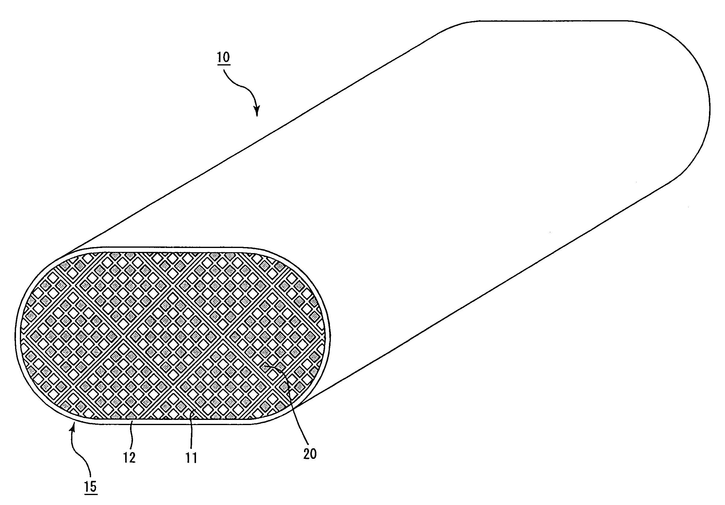
[0137]The same processes as those of Example 1 except the following were carried out to prepare each honeycomb structural body 10: the angle that was formed by the pattern of the sealing material layer among honeycomb units on a cross section perpendicular to the longitudinal direction and the major axis in the shape forming the contour of the cross section, and the maximum cross-sectional area perpendicular to the longitudinal direction of the honeycomb unit were respectively set to the values listed on Table 1; the ceramic block was manufactured by using a heat resistant sealing material (adhesive) paste containing alumina fibers having a fiber length of 20 μm (30% by weight), silicon carbide particles having an average particle size of 0.6 μm (21% by weight), silica sol (15% by weight), carboxymethyl cellulose (5.6% by weight) and water (28.4% by weight) as the sealing material (adhesive) paste for bonding the honeycomb units 20; and the sealing material layer was formed on the p...

example 16

[0139]The same processes as those of Example 9 except the following were carried out to prepare each honeycomb structural body 10: the angle that was formed by the pattern of the sealing material layer among honeycomb units on a cross section perpendicular to the longitudinal direction and the major axis in the shape forming the contour of the cross section, and the maximum cross-sectional area perpendicular to the longitudinal direction of the honeycomb unit were respectively set to the values listed on Table 1; the ceramic block was manufactured by using a heat resistant sealing material (adhesive) paste containing alumina fibers having a fiber length of 20 μm (30% by weight), silicon carbide particles having an average particle size of 0.6 μm (21% by weight), silica sol (15% by weight), carboxymethyl cellulose (5.6% by weight) and water (28.4% by weight) as the sealing material (adhesive) paste for bonding the honeycomb units 20; and the sealing material layer was formed on the p...


PUM

PropertyMeasurementUnit
areaaaaaaaaaaa
areaaaaaaaaaaa
angleaaaaaaaaaa

Abstract

A honeycomb structural body includes a ceramic block having a flat shape and including honeycomb units bonded to each other through a sealing material layer, each of the honeycomb units made of porous ceramic and having through holes extending in parallel with one another in a longitudinal direction of the ceramic block and a partition wall interposed between the through holes. The honeycomb structural body further includes a peripheral sealing material layer formed on a peripheral portion of the ceramic block. The sealing material layer is formed such that the sealing material layer abuts against the peripheral sealing layer at an angle in a diagonal direction with respect to a major axis of a contour of the ceramic block in a cross section perpendicular to the longitudinal direction.

Description

CROSS-REFERENCE TO RELATED APPLICATIONS[0001]This application claims benefit of priority to Japanese Patent Application No. 2004-137728, filed on May 6, 2004, and PCT application PCT / JP2004 / 019382, filed on Dec. 24, 2004. The contents of those applications are incorporated herein by reference in their entirety.BACKGROUND OF THE INVENTION[0002]1. Field of the Invention[0003]The present invention relates to a honeycomb structural body that is used as a filter for removing particulates and the like contained in exhaust gases discharged from an internal combustion system such as a diesel engine or the like, a catalyst supporting member and the like.[0004]2. Discussion of the Background[0005]In recent years, particulates, such as soot and the like, contained in exhaust gases that are discharged from internal combustion engines of vehicles, such as buses, trucks and the like, and construction machines and the like, have raised serious problems as those particulates are harmful to the envi...

Claims


Application Information

Patent Timeline
Patent Type & Authority Patents(United States)
IPC IPC(8): B01D39/00B01D39/06B01D39/14B01D39/20B01D46/00B01D46/24B01D53/88B01J23/63B01J27/224B01J32/00B01J35/04B28B1/00C04B37/00C04B38/00F01N3/022F01N3/28
CPCB01D46/2462B01D46/2466B01D53/885B01D53/9454B01J27/224B01J35/04B28B1/002C04B38/0006F01N3/0222F01N3/2828B01D46/2455C04B35/565C04B35/6263C04B35/00C04B38/00C04B41/48C04B41/50B01D46/2451Y10T29/49604B01D46/2459B01D2046/2492B01D2258/012B01J23/63C04B2111/00612C04B2111/0081F01N2450/28Y02T10/22C04B2237/76C04B2237/708C04B2237/368C04B2237/366C04B2237/365C04B2237/361C04B2237/36C04B2237/348Y02T10/20C04B2235/383C04B2235/5224C04B2235/5228C04B2235/5232C04B2235/5264C04B2235/5436C04B2235/5445C04B2235/5472C04B2237/08C04B2237/083C04B2237/09C04B2237/34C04B2237/341C04B2237/343C04B2237/346Y02T10/12B01D46/2486B01D46/2484B01D46/2482B01D39/20B01D53/84
Inventor TAKAHASHI, TOMOHISA
Owner IBIDEN CO LTD
Why Eureka
Try Eureka