
Variable transconductance mixer system

a mixer system and transconductance technology, applied in the field of variable transconductance mixer systems, can solve the problems of affecting the performance of the mixer, the core circuitry of the active mixer is not without significant disadvantages, and the active mixer topologies typically suffer from significant flicker (1/f) noise problems, etc., to achieve cost-effective effects

Active Publication Date: 2010-12-07
QUALCOMM INC
View PDF5 Cites 13 Cited by
  • Summary
  • Abstract
  • Description
  • Claims
  • Application Information

AI Technical Summary

Benefits of technology

[0012]It is yet another object of the present invention to provide a variable transconductance device for a mixer apparatus capable of delivering variable signal power gain in a simple yet cost effective manner.

Problems solved by technology

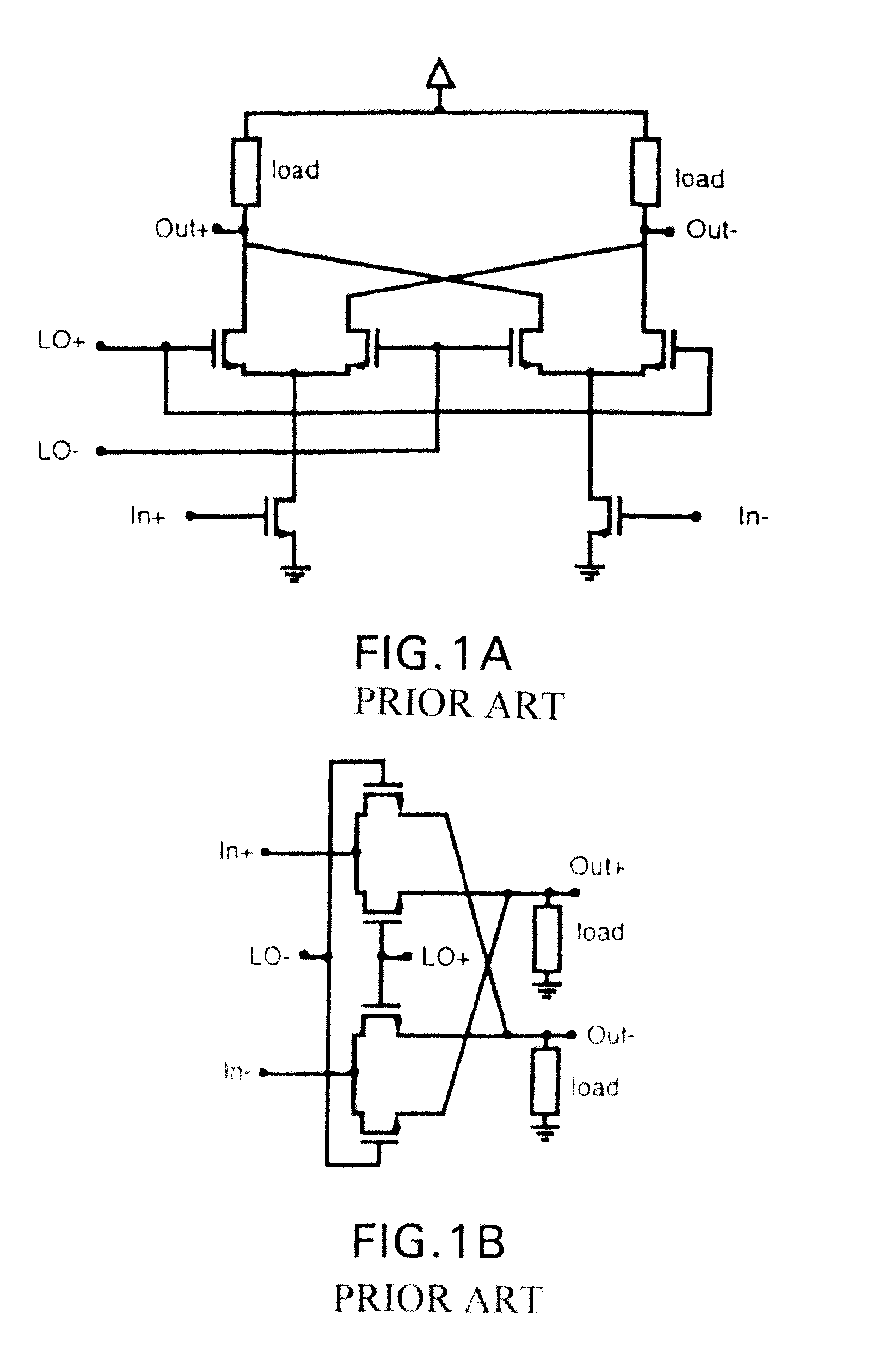
Despite their notable advantages, active mixer topologies typically suffer from significant flicker (1 / f) noise problems.
The flicker noise problem which results from the flow of DC current in the mixer's core circuitry raises serious, even prohibitive, concerns in some radio applications.
Passive mixers of this type, however, are not without their own significant disadvantages.
By definition, passive mixers do not provide power gain, yielding instead a signal power loss.
This makes for more pronounced noise contributions from other processes which follow downstream of the mixer.
Another significant disadvantage of passive type mixers is that, unlike active mixers, they do require large LO swing amplitudes.
Maintaining sufficiently large LO swing amplitudes in this regard requires substantial design challenges to be overcome, which unduly raises costs both in terms of power consumption and overall system complexity.
Also, the requisite LO swing raises prohibitive concerns in some of the more advanced technologies where voltage headroom constraints are highly limiting.

Method used


Image

  • Variable transconductance mixer system
  • Variable transconductance mixer system
  • Variable transconductance mixer system

Examples


Embodiment Construction

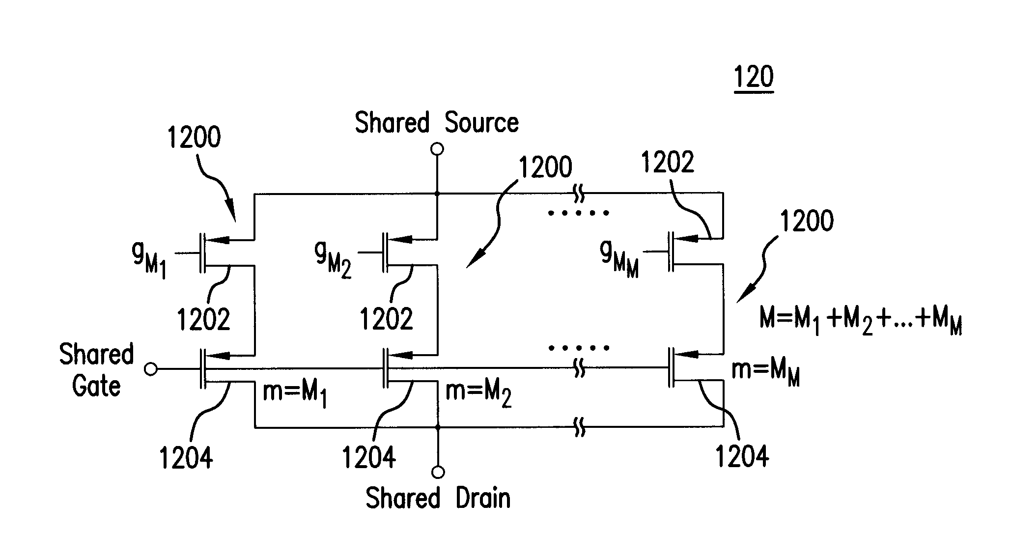
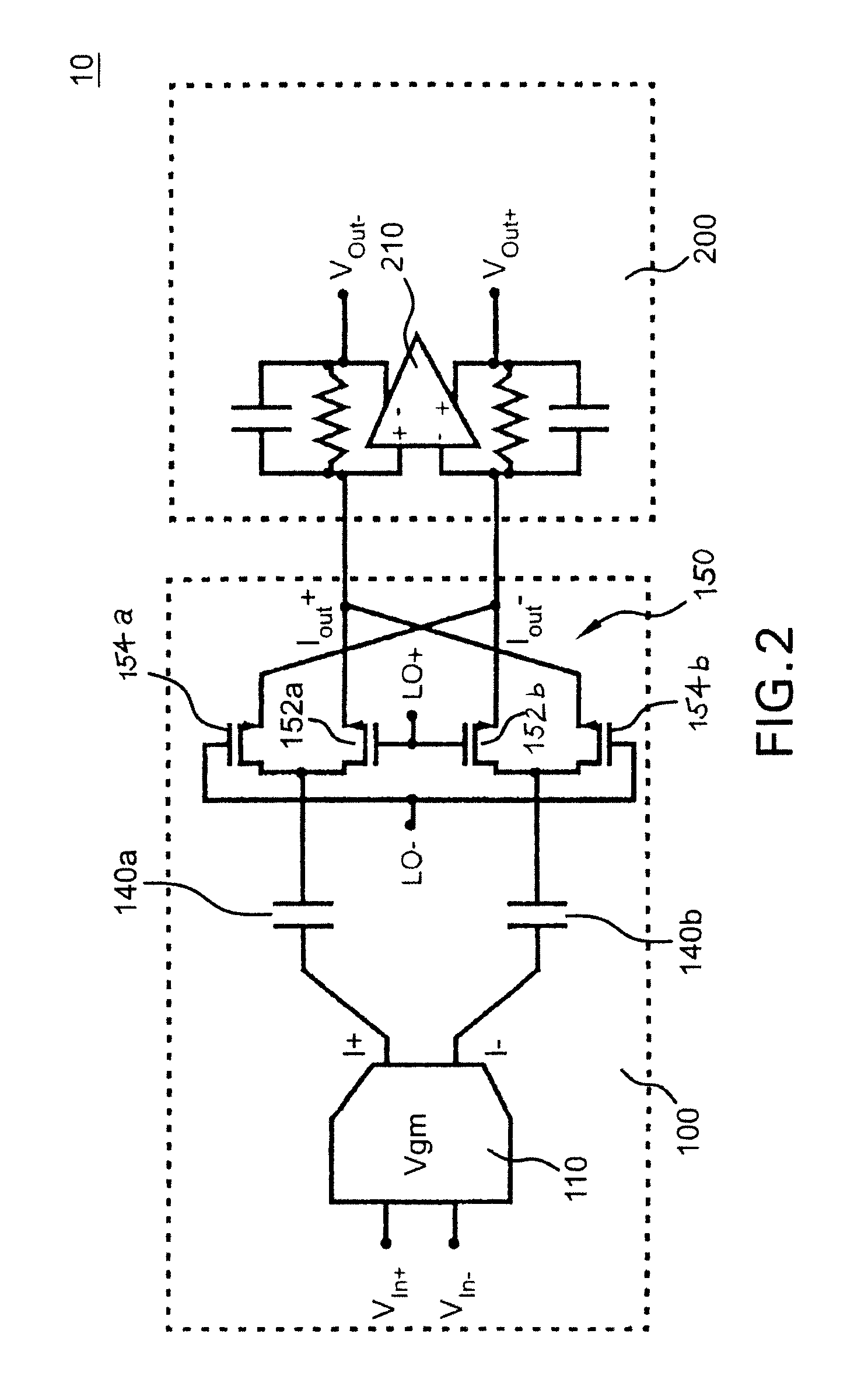
[0025]Referring now to FIG. 2, there is schematically illustrated a variable transconductance mixer system 10 formed in accordance with an exemplary embodiment of the present invention. Generally, the apparatus incorporating variable transconductance mixing system 10 includes in this embodiment a mixer portion 100 which combines the benefits of both passive and active mixer types, and a current-to-voltage converter portion 200 coupled to convert the current signal outputs IOut+, IOut− of the combined mixer portion 100 to corresponding voltage signal outputs VOut+, VOut−. The combined passive-active mixer portion 100 is formed generally by a variable transconductance unit 110 and a passive mixer unit 150 coupled thereto by a pair of DC-blocking capacitors 140a, 140b.

[0026]As shown, the variable transconductance unit 110 receives the positive and negative components, VIn+, VIn− of a differential voltage input signal and generates a pair of corresponding output current signals I+, I− ...


PUM


Abstract

A variable transconductance device for a mixer apparatus is provided. The apparatus includes at least one variable current source circuit having a plurality of selectively enabled current source stages. Each of the current source stages, when enabled, is actuable to establish a conductive path between a first supply level and an output terminal. The device further includes at least one variable transconductance circuit having a plurality of selectively enabled transconductance stages. Each transconductance stage, when enabled, is actuable to establish a conductive path between a second supply level and the output terminal. An output current signal is generated at the output terminal responsive to actuation of the variable transconductance circuit by an input voltage signal, whereby the output current signal exhibits a power gain adjustably determined responsive to the numbers of current source and transconductance stages selectively enabled.

Description

RELATED APPLICATION DATA[0001]This Application is based upon U.S. Provisional Patent Application 60 / 973,143, filed 17 Sep. 2007.BACKGROUND OF THE INVENTION[0002]The subject variable transconductance mixer system is generally directed to a system for receiving an electromagnetic signal and preparing for further processing downstream. More specifically, the subject variable transconductance mixer system is one which may be selectively configured to realize an adjustable power gain in the signal for modulation with a local oscillator (LO) signal, and to do so with minimal noise effect.[0003]In communication systems, electromagnetic signals within a wide range of frequencies and signal attributes are received and processed. One of the initial steps in receiving and processing such signals is to down-convert the received signal to an intermediate frequency by mixing, or modulating, with a local oscillator signal of predetermined frequency. Various mixer topologies are known in the art. T...

Claims


Application Information

Patent Timeline
IPC IPC(8): G06F7/44
CPCH03L7/099H03B5/1228H03B5/1212H03B5/1265H03B5/1253H03B2201/025H03J2200/10
Inventor SAMAVATI, HIRAD
Owner QUALCOMM INC
Learn More