

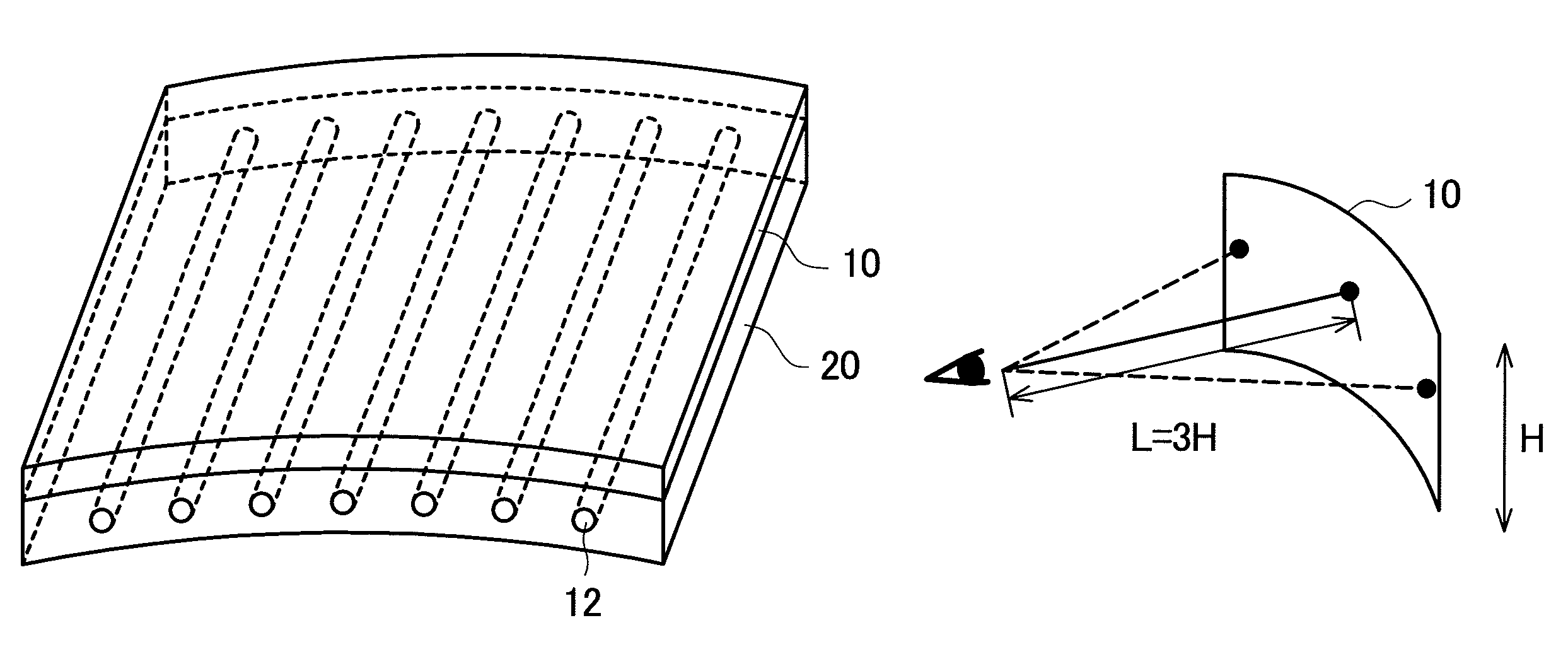
LCD device with plural fluorescent tube backlight for a rectangular curved display surface of a radius of from two to four times as large as the length of the short-side of the rectangular display region
a technology of fluorescent tubes and liquid crystal displays, which is applied in the direction of display devices, lighting and heating apparatus, instruments, etc., can solve the problems of difficult backlight design, difficult to realize flexible liquid crystal displays, and difficult to manufacture display devices, etc., to achieve easy manufacturing of display devices, high reliability, and low cost
- Summary
- Abstract
- Description
- Claims
- Application Information
AI Technical Summary
Benefits of technology
Problems solved by technology
Method used
Image

Examples
embodiment 1
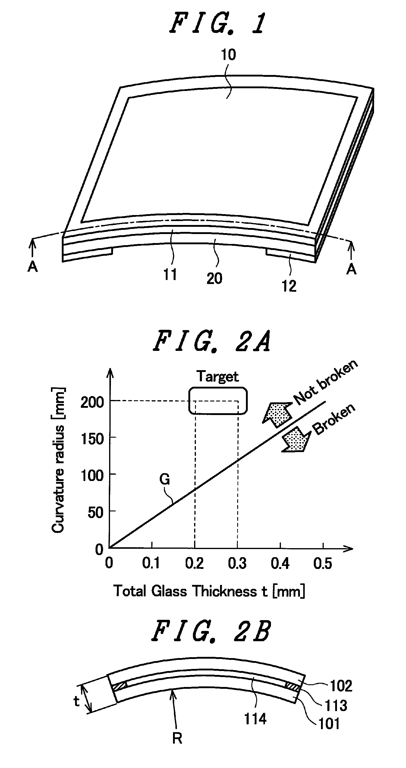
[0050]FIG. 1 is a view showing an appearance of a display device of the embodiment 1. FIG. 1 shows a display having an outwardly projecting screen. Such a display device is used for amusement, that is, for a slot gaming machine or the like, for example. In FIG. 1, a liquid crystal display panel 10 is outwardly curved. As described in “non-patent document 1”, the outwardly-curved liquid crystal display panel 10 may be formed of, for example, a substrate made of plastic. On the other hand, a substrate may be formed using glass and the glass substrate may be made thin to form a liquid crystal display panel 10 having a curved screen.
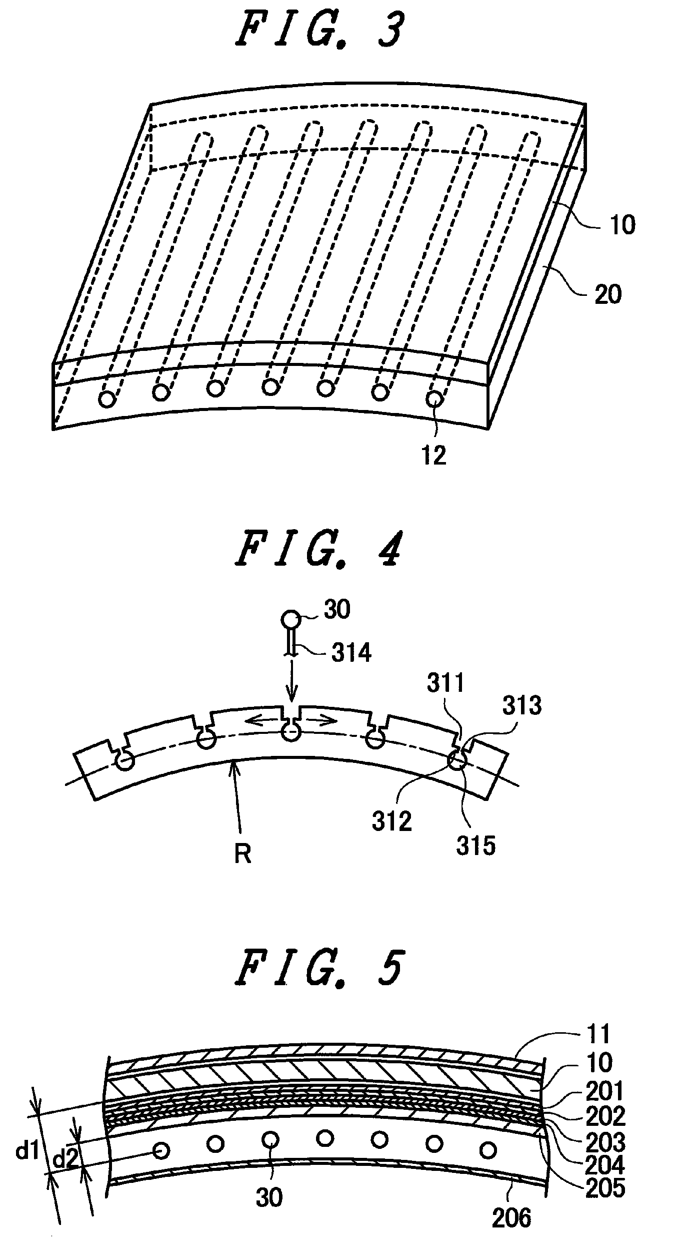
[0051]In FIG. 1, the liquid crystal display panel 10 is covered with a curved frame 11 except for a display part. A backlight 20 is arranged on a back surface of the liquid crystal display panel 10. The backlight 20 is, as described later, constituted of various optical parts and a light source. In this embodiment, the light source is constituted of fluoresc...
embodiment 2
[0082]In the liquid crystal display device of the embodiment 1, the screen of the liquid crystal display device is outwardly projected. An advantage of the present invention which makes use of the liquid crystal display device can also form a recessed screen. By forming the recessed screen, the characteristics of the liquid crystal display device can be further enhanced.
[0083]FIG. 12 shows a viewing angle characteristic of the liquid crystal display panel 10. One of drawbacks in image quality of the liquid crystal display panel 10 lies in a change of brightness, chromaticity or the like depending a screen viewing angle. FIG. 12 shows the viewing angle characteristic of a usual TN-type liquid crystal display device. In FIG. 12, brightness is taken on an axis of ordinates, and brightness when the screen is viewed in the direction perpendicular to the screen is set to 100%. An angle at which the screen is viewed is taken on an axis of abscissas. That is, the angle when the screen is vi...
PUM
 Abstract
Description
Claims
Application Information