Optical switch and optical waveform monitoring device utilizing optical switch
a monitoring device and optical switch technology, applied in multiplex communication, polarisation multiplex system, instruments, etc., can solve the problems of limited operation speed, high-speed signal limit, signal or control signal has the same problem in terms of operation speed, etc., and achieve excellent optical s/n ratio and high switching efficiency
- Summary
- Abstract
- Description
- Claims
- Application Information
AI Technical Summary
Benefits of technology
Problems solved by technology
Method used
Image
Examples
embodiment 1
[0197]FIG. 40 is a diagram describing a configuration of the system for testing characteristics of the optical switch of the present invention. The testing environment is provided below.
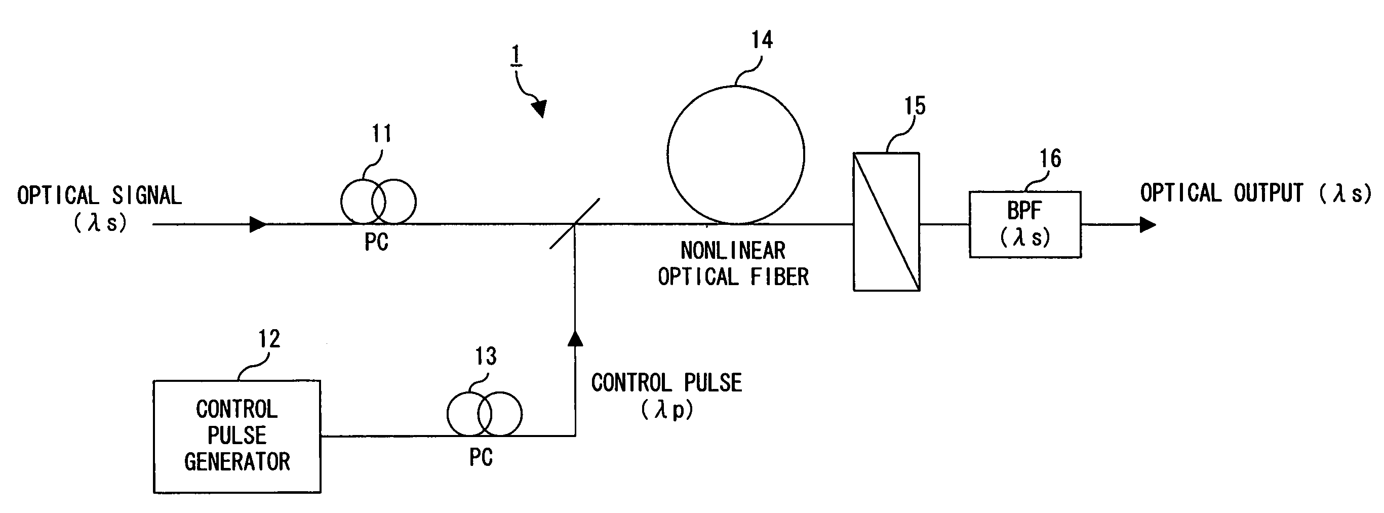
[0198]Highly nonlinear fiber (HNLF) is equivalent to the nonlinear optical fiber 14 in FIG. 1. It is 20 m long and has a third-order nonlinear coefficient γ of 20.4 W−1km−1, a zero dispersion wavelength λ0 of 1579 nm, and a dispersion slope of 0.03 ps / nm2 / km. A first Mode-locked fiber laser (MLFL1) generates a series of pulses with a repetition rate of 10 GHz at a wavelength λs in the C-band. The series of optical pulses is modulated by an LiNbO3 intensity modulator (LN, 10 Gbps, PRBS:223−1), the modulated signal is multiplexed by optical time-division multiplexing to generate a data signal Es of 160-640 Gbps. With control pulse Ep generated by a second mode-locked fiber laser (MLFL2), the data signal Es is fed to the highly nonlinear fiber HNLF. The wavelength of the control pulse Ep is approximatel...
embodiment 2
[0202]Experimental data for optical demultiplexer, which splits a 10 Gbps signal from an optical time-division multiplexed signals Es of 160 Gbps, 320 Gbps, and 640 Gbps is provided below. The pulse width of signal Es at 160 Gbps is 1.6 ps, that of signal Es at 320 Gbps is 0.75 ps, and that of signal Es at 640 Gbps is 0.65 ps. The pulse width of the control pulse Ep is 0.9 ps.
[0203]FIG. 43 is a graph showing measured values of BER (Bit Error Rate) when the reception power PR of the split signal is changed. The average power of the control pulse is +21.8 dBm (equivalent to peak power=15 W). The average power of the input signal Es of 160 Gbps to the optical switch is −5 dBm.
[0204]At 160 Gbps, bit error rates for each signal wavelength λs=1535 nm, 1540 nm, 1550 nm, and 1560 nm are measured. As a result, error-free operation (BER=10−9) with a power penalty of less than 0.2 dB is achieved for all wavelengths in the C-band. Signals with 320 Gbps and 640 Gbps, error-free operation is achi...
embodiment 3
[0205]Signal waveforms observed with an oscilloscope after sampling utilizing the optical switch of the present invention are shown. FIG. 44A through FIG. 44E show the observed eye diagrams when the pulse width conditions are the same as explained in Embodiment 2. The sampling rate is 311 MHz. Excellent eye diagrams are obtained throughout the range of 160 through 640 Gbps. Such fine time resolution is a great contribution to the implementation of optical sampling with high contrast over the entire range of the C-band.
[0206]The following document provides descriptions of the embodiments 1 through 3 explained above. S. Watanabe, et al. “Novel Fiber Kerr-Switch with Parametric Gain: Demonstration of Optical Demultiplexing and Sampling up to 640 Gb / s”, 30th European Conference on Optical Communication (ECOC 2004), Stockholm, Sweden, September 2004, Post-deadline paper Th4.1.6, pp 12-13.
PUM
| Property | Measurement | Unit |
|---|---|---|
| angle | aaaaa | aaaaa |
| angle | aaaaa | aaaaa |
| angle | aaaaa | aaaaa |
Abstract
Description
Claims
Application Information
 - R&D
- Intellectual Property
- Life Sciences
- Materials
- Tech Scout
- Unparalleled Data Quality
- Higher Quality Content
- 60% Fewer Hallucinations
Browse by: Latest US Patents, China's latest patents, Technical Efficacy Thesaurus, Application Domain, Technology Topic, Popular Technical Reports.
© 2025 PatSnap. All rights reserved.Legal|Privacy policy|Modern Slavery Act Transparency Statement|Sitemap|About US| Contact US: help@patsnap.com


