Linear transfer mechanism and transfer robot using the same

a transfer mechanism and transfer robot technology, applied in mechanical control devices, instruments, furnaces, etc., can solve the problems of difficult to provide accurate linear transfer movement, distorted link arms such as the above-mentioned two parallelogram link types, and affecting the production efficiency of the system, so as to reduce production costs, prevent deformation of the guide member, and balance the weight of the guide member

Active Publication Date: 2010-12-14
DAIHEN CORP
View PDF12 Cites 5 Cited by
  • Summary
  • Abstract
  • Description
  • Claims
  • Application Information

AI Technical Summary

Benefits of technology

[0011]The present invention has been proposed under the above-described circumstances. It is therefore an object of the present invention to provide a linear transfer mechanism capable of ensuring an accurate linear transfer path with a simple structure, and a transfer robot including the linear transfer mechanism and suitable for use in a vacuum.
[0014]The linear transfer mechanism of the present invention makes use of a belt drive mechanism. Advantageously this feature enables one to readily deal with an increased travel distance of the transfer carriage. Further, since both the drive mechanism and the drive source are supported by the guide member, these two units can be disposed adjacent to each other, which contributes to simplification of the structure of a belt drive mechanism from the drive source to the transfer carriage. Specifically, a motor (an example of the drive source) and a drive pulley (a constituent part of the drive mechanism) maybe disposed close to each other. In this instance, the drive pulley may be connected directly or via a simple reduction mechanism with the output shaft of the drive source motor. With such an arrangement, it is possible to shorten the power transmission route from the drive source to the transfer carriage, thereby reducing power transmission loss in the drive mechanism. Accordingly the drive source may have a small output capacity, which then contributes to space saving and power saving. Another advantage of disposing the drive source near the transfer carriage is that the linear transfer mechanism occupies only a smaller space.
[0016]With this arrangement, it is possible to ensure a reliable operation of the belt drive mechanism while simplifying the structure of the drive mechanism.
[0021]With the above arrangement, the weight of the guide member is well balanced, so that deformation of the guide member is prevented. Further, the first and second drive mechanisms can be arranged symmetrically with respect to the center of the guide member to correspond to the positions of the drive sources. In this instance, the two driving mechanisms may be the same in structure so as to cut down the production cost.

Problems solved by technology

Likewise, in the field of liquid crystal displays, the panel size tends to become larger.
However, these trends have caused a problem that a link arm such as the above-mentioned two parallelogram link type is distorted in the vertical direction by the weight of the work and the hand, especially when the link arm is extended.
Unfavorably, this makes it difficult to provide an accurate linear transfer movement.
With this arrangement, the drive mechanism that transmits the drive power from the motor to the transfer carriages needs to transmit the power over a long distance, and its structure tends to become complicated.
Also, the long power transmission route may give rise to a greater power transmission loss in the drive mechanism.

Method used


Image

  • Linear transfer mechanism and transfer robot using the same
  • Linear transfer mechanism and transfer robot using the same
  • Linear transfer mechanism and transfer robot using the same

Examples


Embodiment Construction

[0035]Preferred embodiments of a linear transfer mechanism according to the present invention and a transfer robot using the same transfer mechanism will be described below with reference to the drawings.

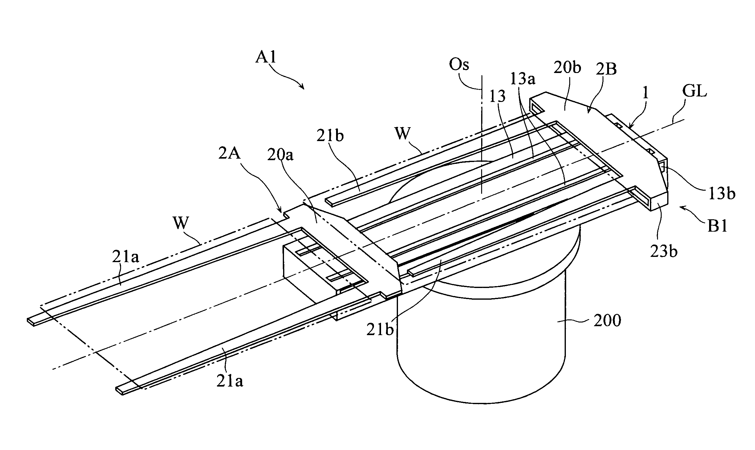
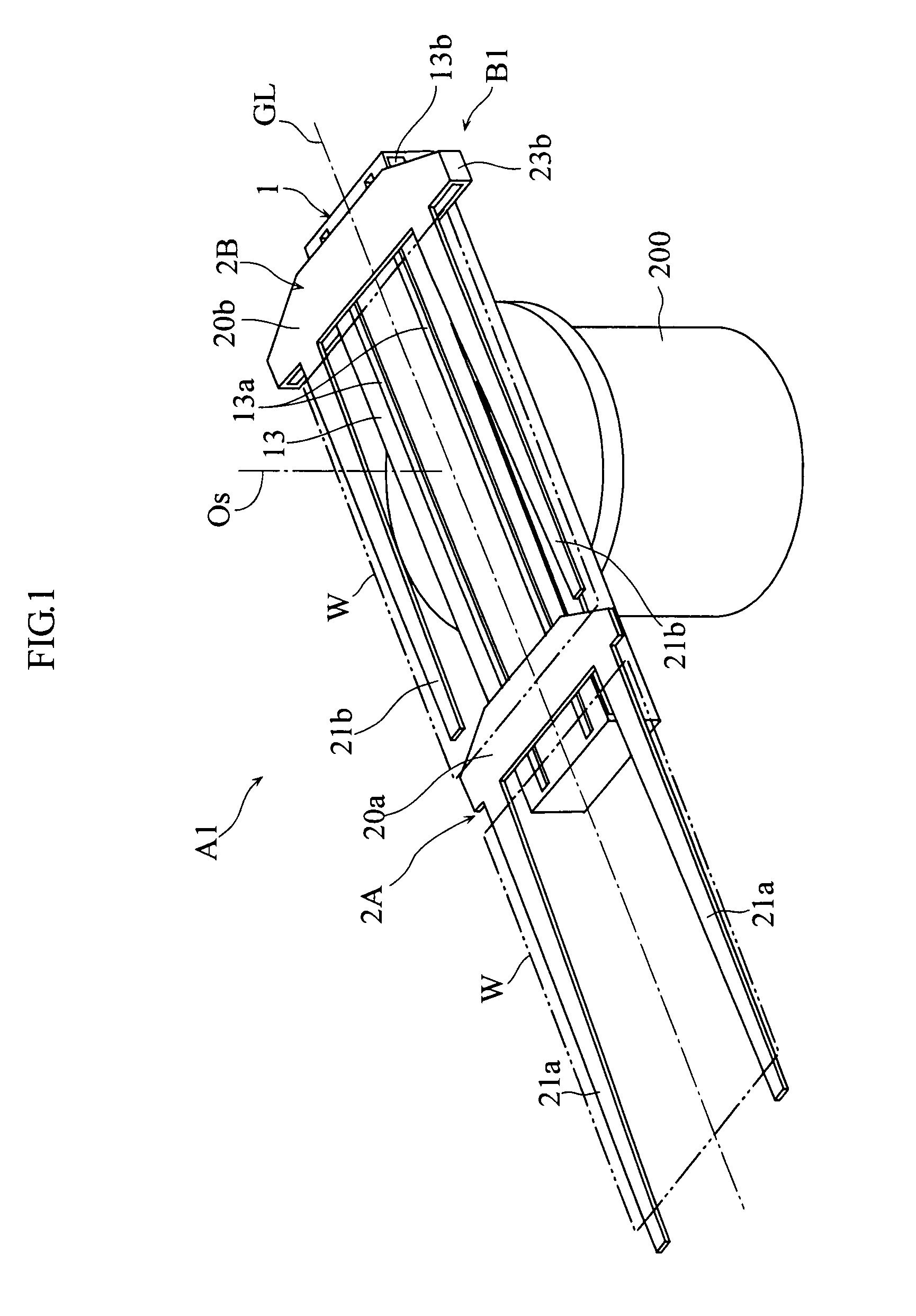
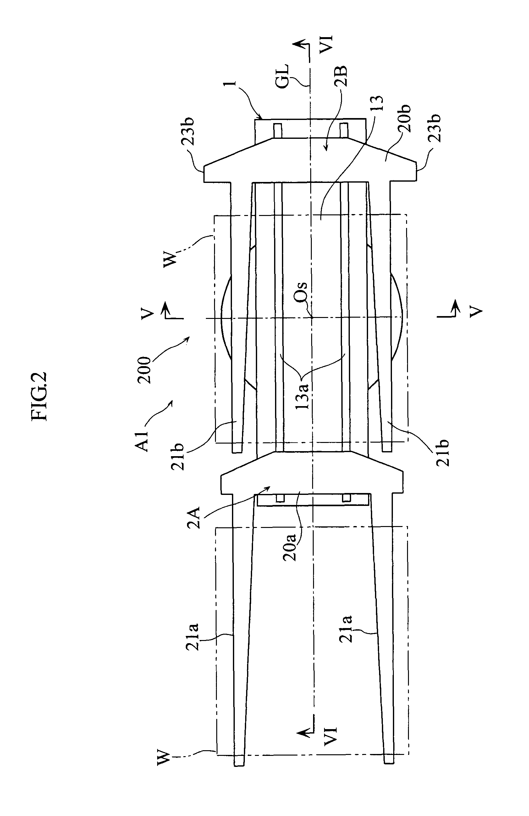
[0036]FIG. 1 through FIG. 8 show a transfer robot according to the present invention. As shown in FIG. 1 through FIG. 4, a transfer robot A1 includes a linear transfer mechanism B1. The transfer mechanism B1 is rotatable relative to a fixed base 200 about a swivel axis Os, while also being vertically movable. The linear transfer mechanism B1 generally includes a table-like guide member 1, and two transfer carriages 2A, 2B which are movable along a horizontal linear transfer path GL arranged on the guide member 1. The first transfer carriage 2A and the second transfer carriage 2B are provided with hands 21a, 21b respectively, for carrying a thin work W such as a glass substrate to be used for a liquid crystal panel.

[0037]As clearly shown in FIG. 5, the fixed base 200 includes a gener...


PUM


Abstract

A linear transfer mechanism includes a guide member, a transfer carriage movable along a horizontal linear transfer path provided on the guide member, and a drive mechanism provided with a drive pulley and an output belt wound around the drive pulley for reciprocating movement in a reciprocating movement section in parallel to the transfer path. The transfer mechanism also includes a drive source for driving the drive pulley. The transfer carriage is connected with the output belt of the drive mechanism by a connecting member. Both the drive mechanism and the drive source are supported by the guide member.

Description

BACKGROUND OF THE INVENTION[0001]1. Field of the Invention[0002]The present invention relates to a linear transfer mechanism and also to a transfer robot incorporating a linear transfer mechanism. In particular, the present invention relates to a transfer robot configured to move thin works such as a substrate along a straight path.[0003]2. Description of the Related Art[0004]Conventional transfer robots include a type that incorporates a linear transfer mechanism for moving a hand or hands along a straight path. These robots, which are simpler in construction and less expensive than multi-joint robots, are widely used in the field of e.g. manufacturing semiconductor devices or liquid crystal display panels, in which thin works such as wafers and glass substrates are brought into and out of various process chambers.[0005]The linear transfer mechanism used for these transfer robots may be of a link-arm type using a combination of two parallelogram links (see JP-A-H10-6258 for example...

Claims


Application Information

Patent Timeline
Patent Type & Authority Patents(United States)
IPC IPC(8): B66C23/00
CPCB25J9/041B25J9/104H01L21/68707B25J18/04Y10T74/20305H01L21/67H01L21/68
Inventor URATANI, TAKAFUMIYODA, HIROKAZUSADO, DAISUKEOKAMOTO, AKIRA
Owner DAIHEN CORP
Why Eureka
Try Eureka