
Oil preheater for a multi oil burner

a multi-oil burner and oil preheater technology, which is applied in the direction of burners, combustion types, combustion processes, etc., can solve the problems of large electricity consumption of prior art inventions, large amount of discarded oil disposal, and large amount of waste oil, so as to improve the dependability of a multi-oil combustion system, minimize preheat temperature fluctuations, and reduce the effect of preheating temperature fluctuations

Inactive Publication Date: 2010-12-14
BECHARD RYAN THOMAS
View PDF14 Cites 3 Cited by
  • Summary
  • Abstract
  • Description
  • Claims
  • Application Information

AI Technical Summary

Benefits of technology

[0030]b. to provide a multi oil preheat device that eliminates the creation of carbonized oil and eliminates the excessive maintenance costs involved with carbon removal.
[0036]h. to provide a multi oil combustion preheat system that can use combustion heat for preheating oil that is more efficient and costs less to operate.

Problems solved by technology

Considerable waste oil is generated as a result of the spent oil garnered from the crankcases of millions of automobiles and trucks whenever the oil is changed.
The disposal of the vast quantities of discarded oil constitutes a great problem.
Unfortunately, many people choose to illegally dump oil rather than pay to have it properly disposed.
While large waste oil generators often receive a small reimbursement for their waste oil, smaller generators, usually end up paying to have it removed off site.
First, and most importantly, because heavier oil fuels are too thick to atomize and spray at ambient temperature, they must be preheated.
Second, is the atomizing of heated oil.
Third, is igniting the atomized oil.
These prior art inventions all consume a significant amount of electricity to preheat oil for combustion.
These electrically preheated burners loose a percentage of their oil energy savings due to their high electrical consumption.
Another disadvantage with prior art's preheat devices is that thermostatically controlled electrical elements are slow to react.
These temperature swings mandate frequent maintenance and create many problems within a combustion system.
Within the prior art's electrically heated preheat device, oil is vulnerable to overheating at the high peak of an electrical element's temperature swing.
Over heated oil produces carbon crystals within the preheat device causing coagulation and clogging of the oil passageway and nozzle resulting in equipment failure.
Oil is vulnerable to carbonization at temperatures as low as 90 degrees Centigrade.
This often happens before prior art's thermostat turns on the electric heating elements because the thermostat is slow to react to the oil temperature.
When oil cools, it thickens, thus reducing the quality of oil atomization as the oil droplet size increases.
This unburned oil fuel accumulation can propose a serious hazard to the end user.
Whereas oil is vulnerable to carbonization from direct overheating, a liquid such as a water glycol solution is not.
A significant disadvantage of using prior art's electrical elements to preheat oil is their tendency to overheat the oil.
Over time, this causes the oil to carbonize inside the preheat device thus creating many problems in the combustion process.
The carbon crystals created by overheated oil, will plug the nozzle causing equipment failure.
The coagulation of carbonized oil inside the passageways of the prior art's preheat device restricts the oil flow causing inconsistent combustion and eventual equipment failure.
This problem is so prevalent in the industry that manufactures, or their distributors, offer customer training on overhauling procedures.
Overhauling costs an owner of the prior art inventions a significant amount of time and money to keep the system operable.
Another disadvantage of using thermostatically controlled electric elements to preheat oil is that of reduced safety.
In the event that the prior art's control system were to fail causing an element to remain energized, a potential fire hazard could occur.
Prior art's control system is extremely complex with sensors, switches, wiring and controllers to prevent a hazardous condition.
In summary, using thermostatically controlled electrical elements to preheat oil is inefficient, undependable, potentially hazardous and is expensive to maintain.
The prior art's preheat systems involve many moving parts, sensors, wiring, controllers and components vulnerable to failure causing equipment malfunction and a hazardous condition.

Method used


Image

  • Oil preheater for a multi oil burner
  • Oil preheater for a multi oil burner
  • Oil preheater for a multi oil burner

Examples


Embodiment Construction

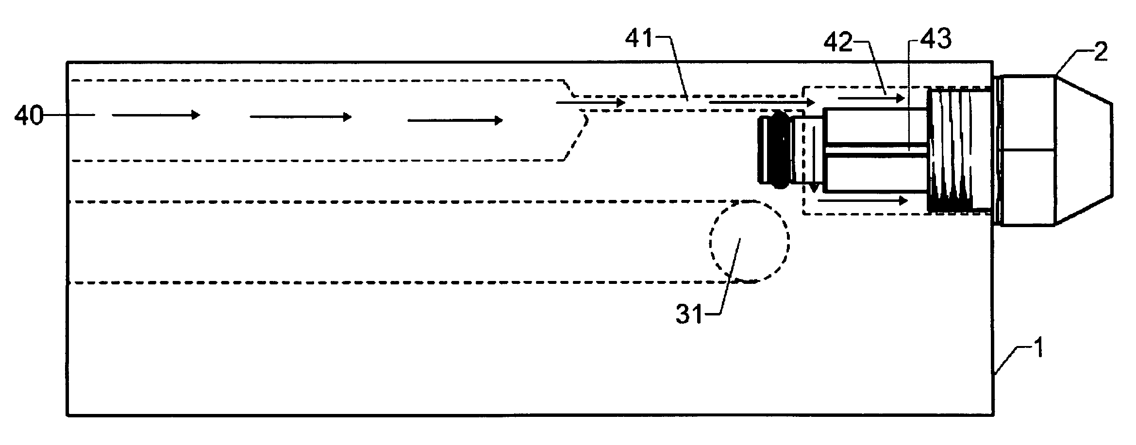
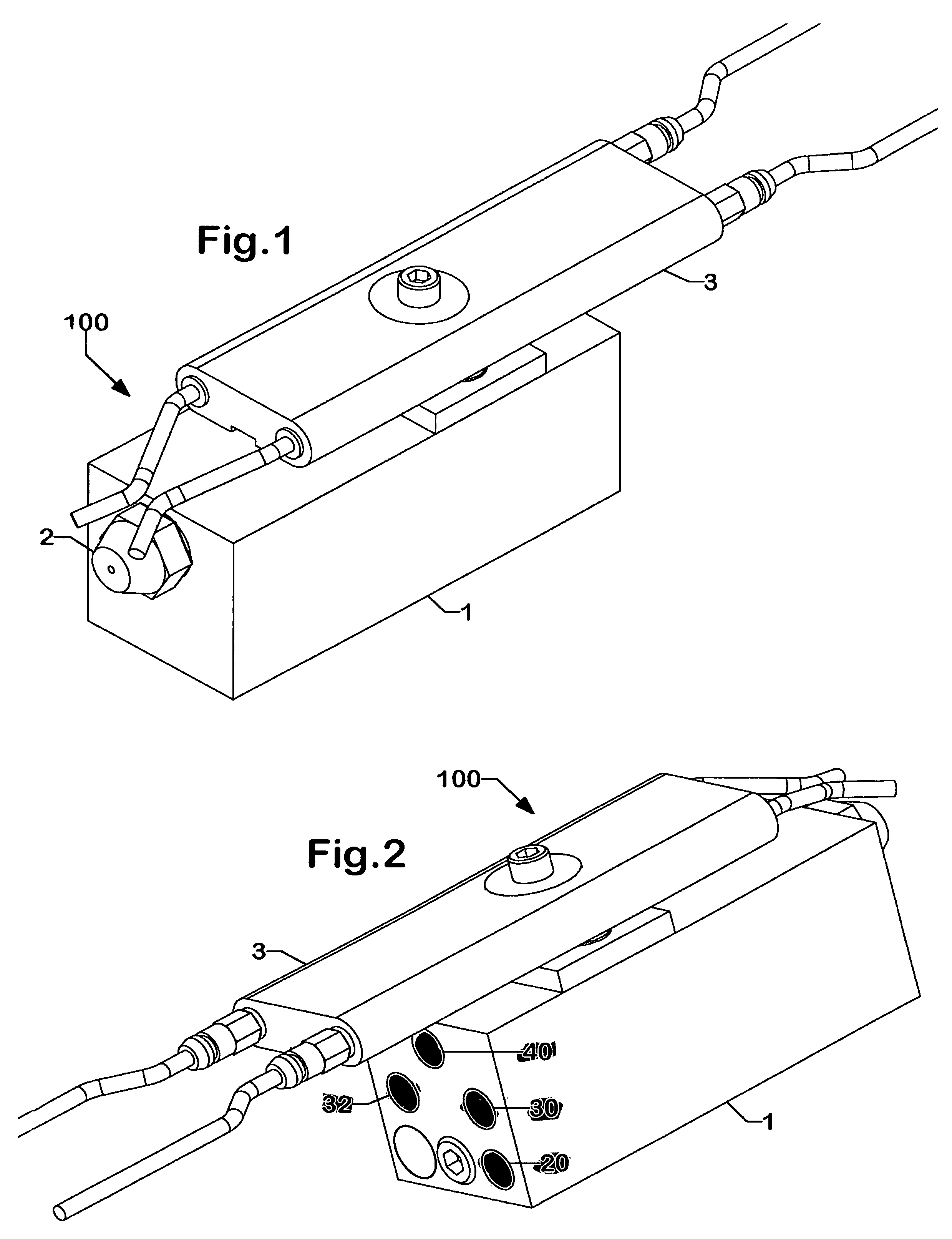
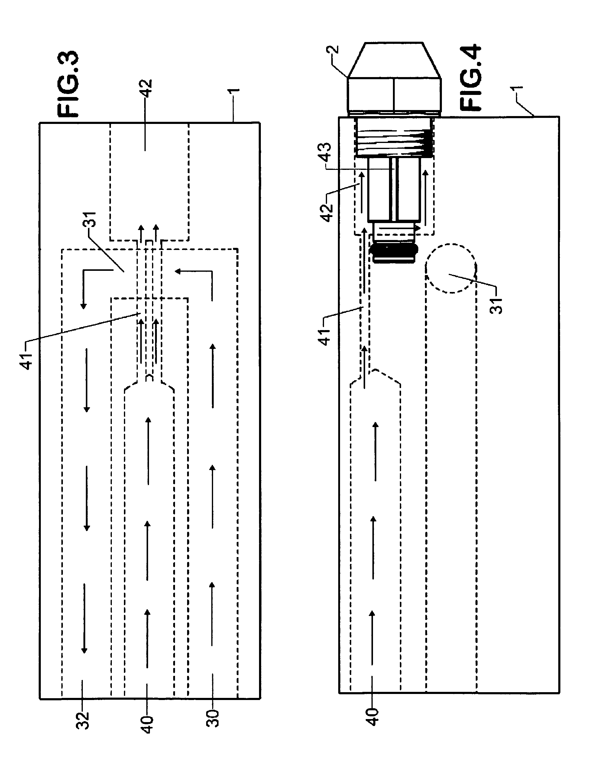
[0045]A preferred embodiment of the present liquid heated multi oil preheat invention is illustrated in FIGS. 1 and 2 isometric views. The present invention, a liquid heated multi oil preheat device 1 is shown with a nozzle 2 and an igniter 3 attached to it which provide a means of atomizing and igniting the preheated oil as was previously described. This assembly comprising of preheat device 1, nozzle 2 and igniter 3 will be referred to as assembly 100. Within preheat device 1, the materials of combustion are directed and distributed to nozzle 2 via machined channel circuits. Inside preheat device 1 there is a heated liquid passageway which allows a heated liquid to circulate within while conductively transferring heat energy through preheat device 1 to oil and compressed air as it passes through preheat device 1 to nozzle 2. These channels will be discussed later in more detail with FIGS. 3, 4, 5 and 6. In its simplest form, preheat device 1 is a liquid to liquid heat exchanger. N...


PUM


Abstract

A device and method of preheating oil for use in a multi oil burner that uses a heated liquid to convey heat energy to oil. The device is made of a thermally conductive material which has a passageway for oil and a passageway for a heated liquid. Heat energy from the heated liquid conductively transfers to the oil within the device. This method of preheating oil for combustion eliminates carbon creation and minimizes oil preheat temperature fluctuations thereby significantly lowering the cost and maintenance to operate a multi oil combustion system.

Description

CROSS REFERENCE TO RELATED APPLICATIONS[0001]This application claims the benefit of provisional patent application Ser. No. 60 / 320,227, filed on May 28, 2003 by Ryan Bechard.BACKGROUND OF INVENTION[0002]This invention relates generally to heating appliances such as furnaces and boilers, specifically for the purpose of preheating heavy oil fuels for combustion.[0003]Considerable waste oil is generated as a result of the spent oil garnered from the crankcases of millions of automobiles and trucks whenever the oil is changed. The disposal of the vast quantities of discarded oil constitutes a great problem. Some waste oil is cleaned and is then resold. Unfortunately, many people choose to illegally dump oil rather than pay to have it properly disposed.[0004]When properly performed, efficient and complete incineration of waste oil provides many benefits. While large waste oil generators often receive a small reimbursement for their waste oil, smaller generators, usually end up paying to ...

Claims


Application Information

Patent Timeline
Patent Type & Authority Patents(United States)
IPC IPC(8): F23D11/44F23CF23Q3/00
CPCF23D11/445
Inventor BECHARD, RYAN THOMAS
Owner BECHARD RYAN THOMAS
Learn More