Determining a viewpoint for navigating a virtual camera through a biological object with a lumen

a virtual camera and viewpoint technology, applied in the field of virtual endoscopy, can solve the problems of affecting the visual requiring heavy patient sedation, and affecting the image quality of the image, and achieve the effect of increasing the angle separation

Inactive Publication Date: 2010-12-14
TOSHIBA MEDICAL VISUALIZATION SYST EURO
View PDF18 Cites 11 Cited by
  • Summary
  • Abstract
  • Description
  • Claims
  • Application Information

AI Technical Summary

Benefits of technology

[0015]Thus the method allows images to be rendered from locations along a virtual endoscopy flight path (navigation path) in a way that appears to tend to align the camera with an artificial gravity direction. This helps to provide a user with a more easily interpretable, and less disorienting, virtual endoscopy experience. Furthermore, because the images tend to align with a direction that can be the same in different data sets, flythrough of different data sets representing the same lumen will tend to adopt the same camera orientation when in the same parts of the lumen. This allows for easier comparison of virtual endoscopy flythroughs through different data sets since features which are attached to the lumen wall, e.g. polyps in a virtual colonoscopy, will tend to appear in the same part of corresponding images in different flythroughs. This is because the camera orientation is registered with respect to a selected direction with respect to patient orientation. Furthermore, by orienting the virtual camera in accordance with a rotation from the initial orientation towards the bias direction by a fractional amount of the offset angle which varies according to the initial orientation, a balance between providing an observer with a perception of gravity, and maintaining a preferred view direction so far as the geometry of the lumen is concerned and avoiding potential barrel rolling of the virtual camera can be provided.
[0019]In some embodiments, the fractional amount may vary between zero and unity if the offset angle is within a predetermined partial-rotation range. For example, in embodiments where the above-referred to predetermined full-rotation threshold and predetermined no-rotation threshold are employed, the predetermined partial-rotation range may run between these thresholds. Alternatively, the predetermined partial-rotation range may span all possible offset angles (0° to 180°). For example, the predetermined partial-rotation range may have lower boundary selected from the group consisting of 0°, 1°, 2°, 3°, 4°, 5°, 6°, 7°, 8°, 9°, 10°, 11°, 12°, 13°, 14° and 15° and an upper boundary selected from the group consisting of 15°, 20°, 25°, 30°, 35°, 40°, 45°, and 50°. The fractional amount may, for example, decrease linearly, or exponentially, with increasing offset angle within the predetermined partial-rotation range. By varying the fractional amount in this way, the user is provided with the perception of an increasing gravitational force as the camera gets closer to being aligned with the bias direction. This has been found to reduce user disorientation.
[0022]In cases where the fractional amount varies according to an angular separation between a predetermined direction in the data set and a view direction of the virtual camera for the initial orientation, the fractional amount may be zero if the angular separation is less than a predetermined no-rotation threshold. This helps to avoid alarming barrel rolls that may otherwise occur as a flight path changes direction about the perceived vertical which is aligned with the predetermined direction (whether is heading “up” or “down”). The predetermined no-rotation threshold may be selected from the group consisting of 1°, 2°, 3°, 4°, 5°, 6°, 7°, 8°, 9°, 10°, 11°, 12°, 13°, 14°, 15°, 16°, 17°, 18°, 19° and 20° (it being understood that the angular separation may be measured from “up” or “down” along the predetermined direction).
[0023]Furthermore, the fractional amount may be unity if the angular separation is greater than a predetermined full-rotation threshold. For example, the predetermined full-rotation threshold may be selected from the group consisting of 15°, 20°, 25°, 30°, 35°, 40°, 45° and 50°. This ensures the full effects of the perceived virtual gravity can be provided when there is little risk of barrel roll because the flight path is significantly far from being aimed directly “up” or “down”.
[0024]In some embodiments, the fractional amount may vary between zero and unity if the angular separation is within a predetermined partial-rotation range. For example, in embodiments where the above-mentioned predetermined full-rotation threshold and predetermined no-rotation threshold for the angular separation are employed, the predetermined partial-rotation range may run between these thresholds. Alternatively, the predetermined partial-rotation range may span all possible angular separations, i.e., 0° to 90° (since angular separation can be measured from either “up” of “down” along the predetermined direction, it is only necessary to consider this range). For example, the predetermined partial-rotation range may have lower boundary selected from the group consisting of 0°, 1°, 2°, 3°, 4°, 5°, 6°, 7°, 8°, 9°, 10°, 11°, 12°, 13°, 14°, 15°, 16°, 17°, 18°, 19° and 20°, and an upper boundary selected from the group consisting of 15°, 20°, 25°, 30°, 35°, 40°, 45°, and 50°. The fractional amount may, for example, increase linearly, or exponentially, with increasing angular separation within the predetermined partial-rotation range. This has been found to assist user orientation.
[0028]The method may also include determining a desired orientation for the virtual camera relative to the data set for the selected location based on the geometry of the lumen, determining a relocation angle between the desired orientation of the virtual camera and a previous orientation of the virtual camera, and determining the initial orientation of the virtual camera to be the desired orientation if the relocation angle is greater than a relocation angle threshold, and otherwise maintaining the previous orientation as the initial orientation. This has been found to help increase the perceived smoothness of a flythrough. The relocation angle threshold may, for example, be selected from the group consisting of 1°, 2°, 3°, 4°, 5°, 6°, 7°, 8°, 9° and 10°.

Problems solved by technology

The technique is relatively invasive and uncomfortable, and often requires heavy patient sedation.
To navigate the viewpoint through the lumen, a path for the virtual camera to follow is usually determined in advance because even experienced clinicians can have difficulty in manually controlling the virtual camera movement in real time.
A problem with this approach is that the flythrough view can become disorientating for a viewer as the virtual camera rolls, pitches and yaws along what is typically a complex path of loops, twists and turns.
This can hinder the interpretation of the data and in some cases can even cause nausea for the clinician viewing the data.
A further problem arises when a clinician wishes to compare different data sets representing the same lumen.
This makes it difficult to register and reconcile potential features of interest in one data set with those in another.
This lack of registration between images from different flythroughs increases the difficulty in interpreting the data.
Furthermore, it leads to an increased risk that the presence of the same feature in multiple data sets will not be noticed because it appears in different locations in different flythroughs.
This can be problematic because features seen in one data set but missed in another will frequently be discounted as not being of interest.
However, as Huang et al. explain, this approach still leads to sudden twists and turns which can disorient a user and induce nausea.
However, this again leads to camera orientations which are not reproducible in different data sets.
However, a drawback with this approach is that it cannot be performed automatically since a significant amount of clinician input is required to manually identify the teniae coli in the first instance.

Method used


Image

  • Determining a viewpoint for navigating a virtual camera through a biological object with a lumen
  • Determining a viewpoint for navigating a virtual camera through a biological object with a lumen
  • Determining a viewpoint for navigating a virtual camera through a biological object with a lumen

Examples


Embodiment Construction

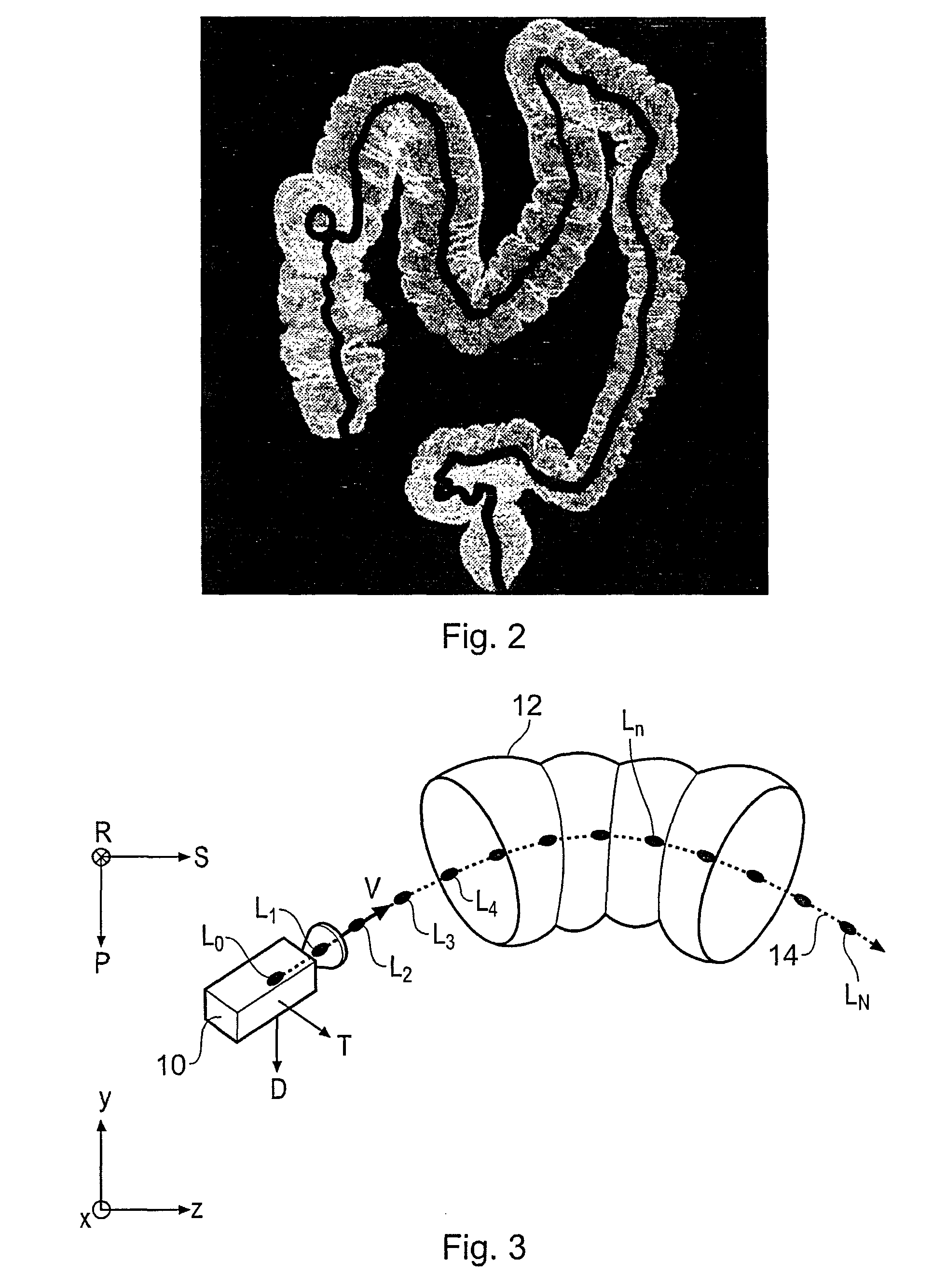
[0051]Virtual endoscopy is often used in the study of the colon. In this context, virtual endoscopy is often referred to as virtual colonoscopy. Embodiments of the invention will hereafter be described by way of example in the specific context of virtual colonoscopy. However, it will be understood that embodiments of the invention may equally be employed in other applications of virtual endoscopy, for example in virtual angiography, virtual bronchoscopy, and also in computer simulated flythroughs of biological structures which are not normally the subject of conventional endoscopy procedures.

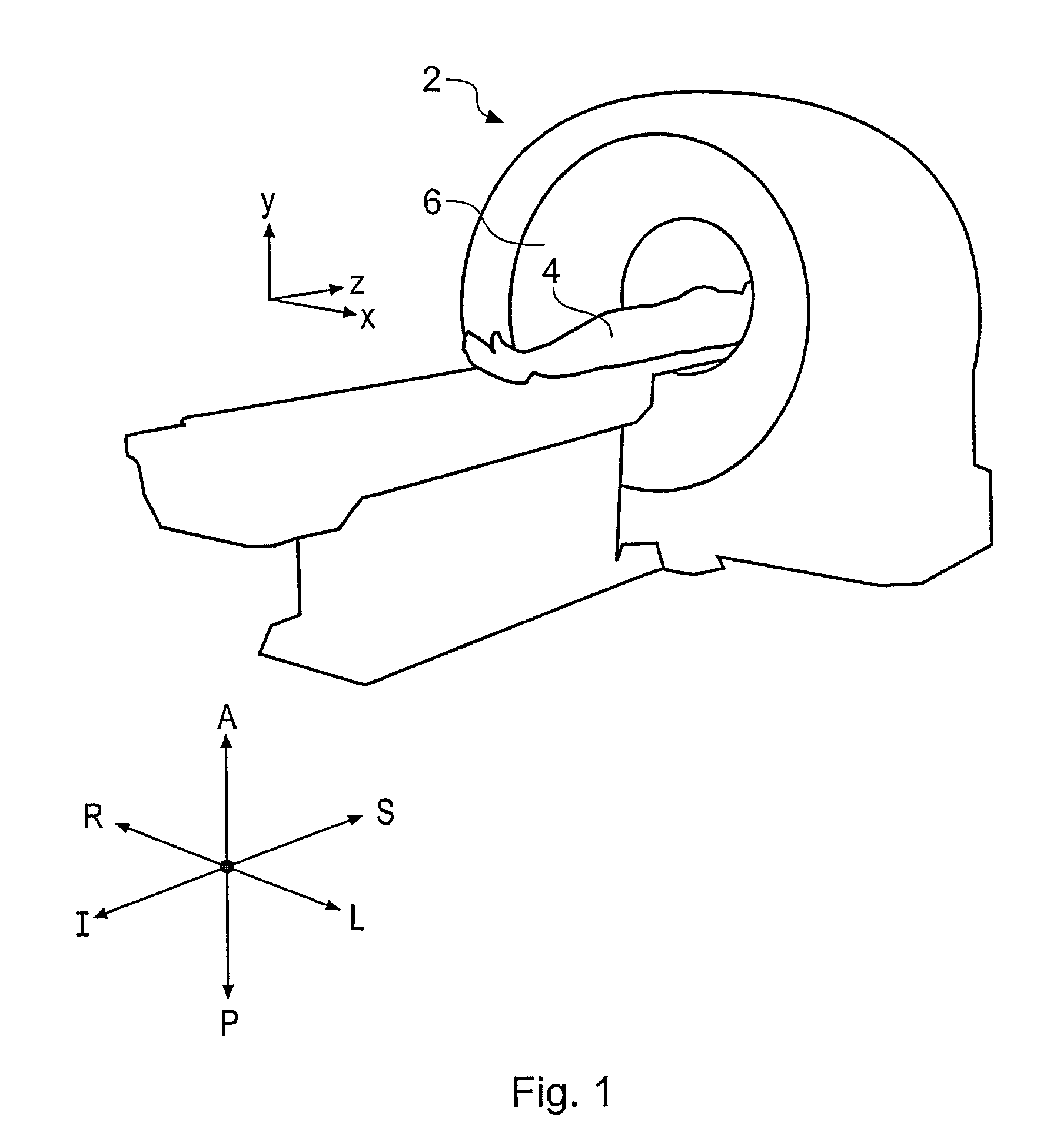
[0052]FIG. 1 is a schematic perspective view of a generic x-ray CT scanner 2 for obtaining a three-dimensional (3D) scan of a patient 4 to provide data suitable for virtual colonoscopy according to an embodiment of the invention. The patient's abdominal region is placed within a circular opening 6 of the CT scanner 2 and a series of x-ray images are taken from directions around the patient. The ...


PUM


Abstract

A method of orienting a virtual camera for rendering a virtual endoscopy image of a lumen in a biological structure represented by a medical image data set, e.g., a colon. The method comprises selecting a location from which to render an image, determining an initial orientation for the virtual camera relative to the data set for the selected location based on the geometry of the lumen, determining an offset angle between the initial orientation and a bias direction; and orienting the virtual camera in accordance with a rotation from the initial orientation towards the bias direction by a fractional amount of the offset angle which varies according to the initial orientation. The fractional amount may vary according to the offset angle and / or a separation between a predetermined direction in the data set and a view direction of the virtual camera for the initial orientation. Thus the camera orientation can be configured to tend towards a preferred direction in the data set, while maintaining a good view of the lumen and avoiding barrel rolling effects.

Description

BACKGROUND ART[0001]The invention relates to the virtual endoscopy, and in particular to determining a viewpoint for navigating a virtual camera through a biological object with a lumen.[0002]Traditional endoscopy involves the use of an endoscope which is inserted into a patient to allow direct visual inspection of, for example, the colon. The technique is relatively invasive and uncomfortable, and often requires heavy patient sedation. Accordingly, virtual endoscopy, which is based on an analysis of medical image data (computer simulated endoscopy), is often preferred.[0003]Patient medical imaging methods, such as computer-assisted tomography (CT), magnetic resonance imaging (MRI), ultrasound and positron-emission tomography (PET), generate large three-dimensional (3D) volume data sets representing all or part of a patient's body. These volume data sets are highly detailed and allow complex studies of the body to be made. Virtual endoscopy is a technique in which a virtual camera i...

Claims


Application Information

Patent Timeline
Patent Type & Authority Patents(United States)
IPC IPC(8): G06K9/00
CPCA61B6/032A61B1/31
Inventor GAULDIE, DAVIDMAYNE, DAVIDMITAL, SWATIWINTER DOEL, THOMAS MACARTHURCRUICKSHANK, KRISTOPHER THOMAS
Owner TOSHIBA MEDICAL VISUALIZATION SYST EURO
Why Eureka
Try Eureka