Rotating optical catheter tip for optical coherence tomography

a technology of optical coherence tomography and rotating shaft, which is applied in the field of catheters, can solve the problems of non-uniform rotation of single fiber oct prototypes, limited duration of saline use, and mechanical drag in the rotating shaft can produce significant distortion and artifacts, and achieve precise depth-resolved imaging of plaques

Inactive Publication Date: 2010-12-14
BOARD OF REGENTS THE TEXAS UNIV SYST +1
View PDF11 Cites 84 Cited by
  • Summary
  • Abstract
  • Description
  • Claims
  • Application Information

AI Technical Summary

Benefits of technology

[0006]The present invention uses depth-resolved light reflection or Optical Coherence Tomography (OCT) to identify the pathological features that have been identified in the vulnerable plaque. In OCT, light from a broad band light source or tunable laser source is split by an optical fiber splitter with one fiber directing light to the vessel wall and the other fiber directing light to a moving reference mirror. The distal end of the optical fiber is interfaced with a catheter for interrogation of the coronary artery during a heart catheterization procedure. The reflected light from the plaque is recombined with the signal from the reference mirror forming interference fringes (measured by an photovoltaic detector) allowing precise depth-resolved imaging of the plaque on a micron scale.
[0007]OCT uses a superluminescent diode source or tunable laser source emitting a 1300 nm wave length, with a 50-250 nm band width (distribution of wave length) to make in situ tomographic images with axial resolution of 2-20 μm and tissue penetration of 2-3 mm. OCT has the potential to image tissues at the level of a single cell. In fact, the inventors have recently utilized broader band width optical sources so that axial resolution is improved to 4 um or less. With such resolution, OCT can be applied to visualize intimal caps, their thickness, and details of structure including fissures, the size and extent of the underlying lipid pool and the presence of inflammatory cells. Moreover, near infrared light sources used in OCT instrumentation can penetrate into heavily calcified tissue regions characteristic of advanced coronary artery disease. With cellular resolution, application of OCT may be used to identify other details of the vulnerable plaque such as infiltration of monocytes and macrophages. In short, application of OCT can provide detailed images of a pathologic specimen without cutting or disturbing the tissue.

Problems solved by technology

Saline use is limited in duration, however, since myocardial ischemia eventually occurs in the distal myocardium.
Mechanical drag in the rotating shaft can produce significant distortion and artifacts in recorded OCT images of the coronary artery.
Unfortunately, because the catheter will always be forced to make several bends between the entry point in the femoral artery to the coronary artery (e.g., the 180 degree turn around the aortic arch), uneven mechanical drag will result in OCT image artifacts As the application of OCT is shifted from imaging gross anatomical structures of the coronary artery to its capability to image at the level of a single cell, non-uniform rotation of the single fiber OCT prototype will become an increasingly problematic source of distortion and image artifact.

Method used


Image

  • Rotating optical catheter tip for optical coherence tomography
  • Rotating optical catheter tip for optical coherence tomography
  • Rotating optical catheter tip for optical coherence tomography

Examples


first embodiment

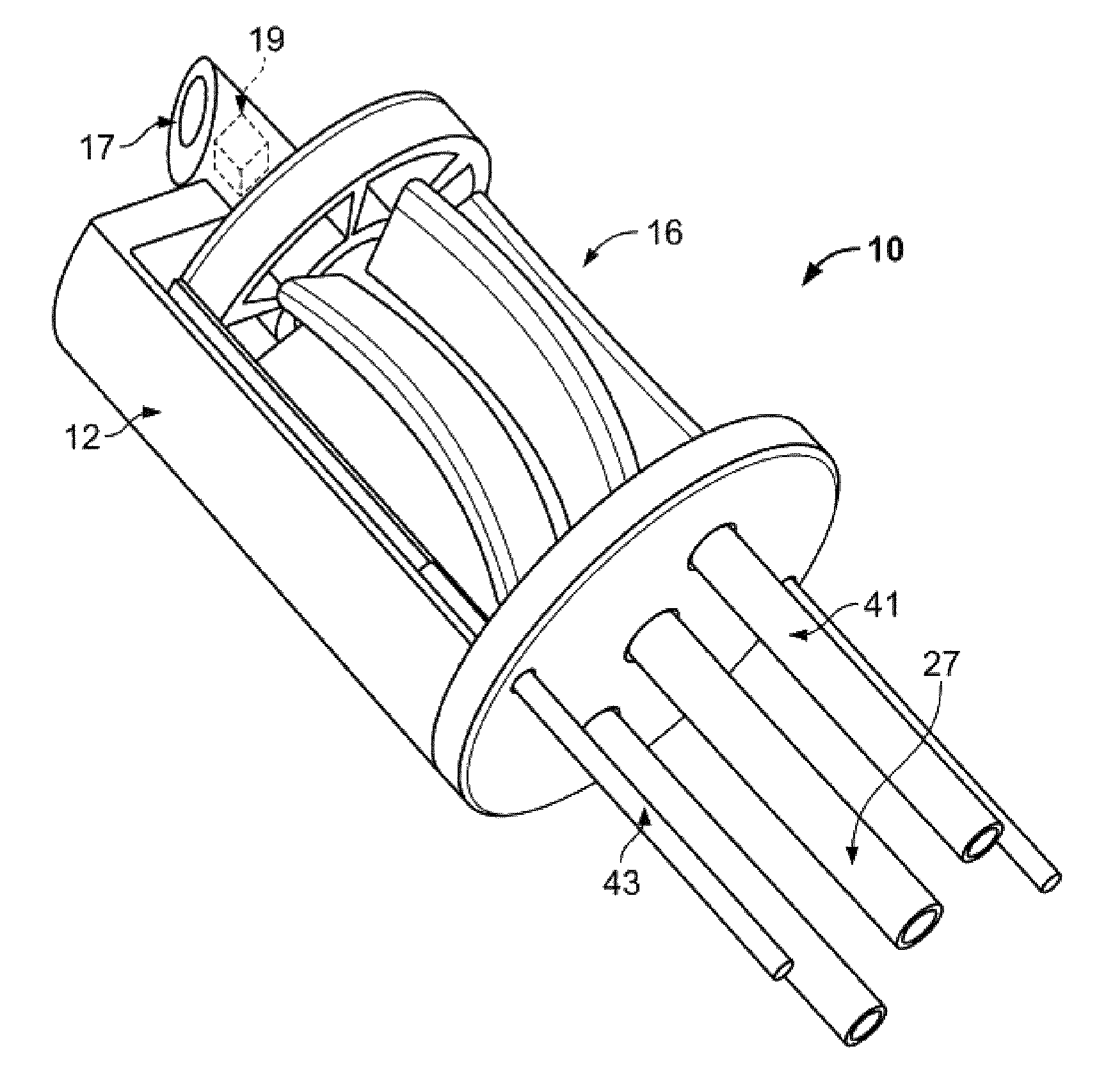
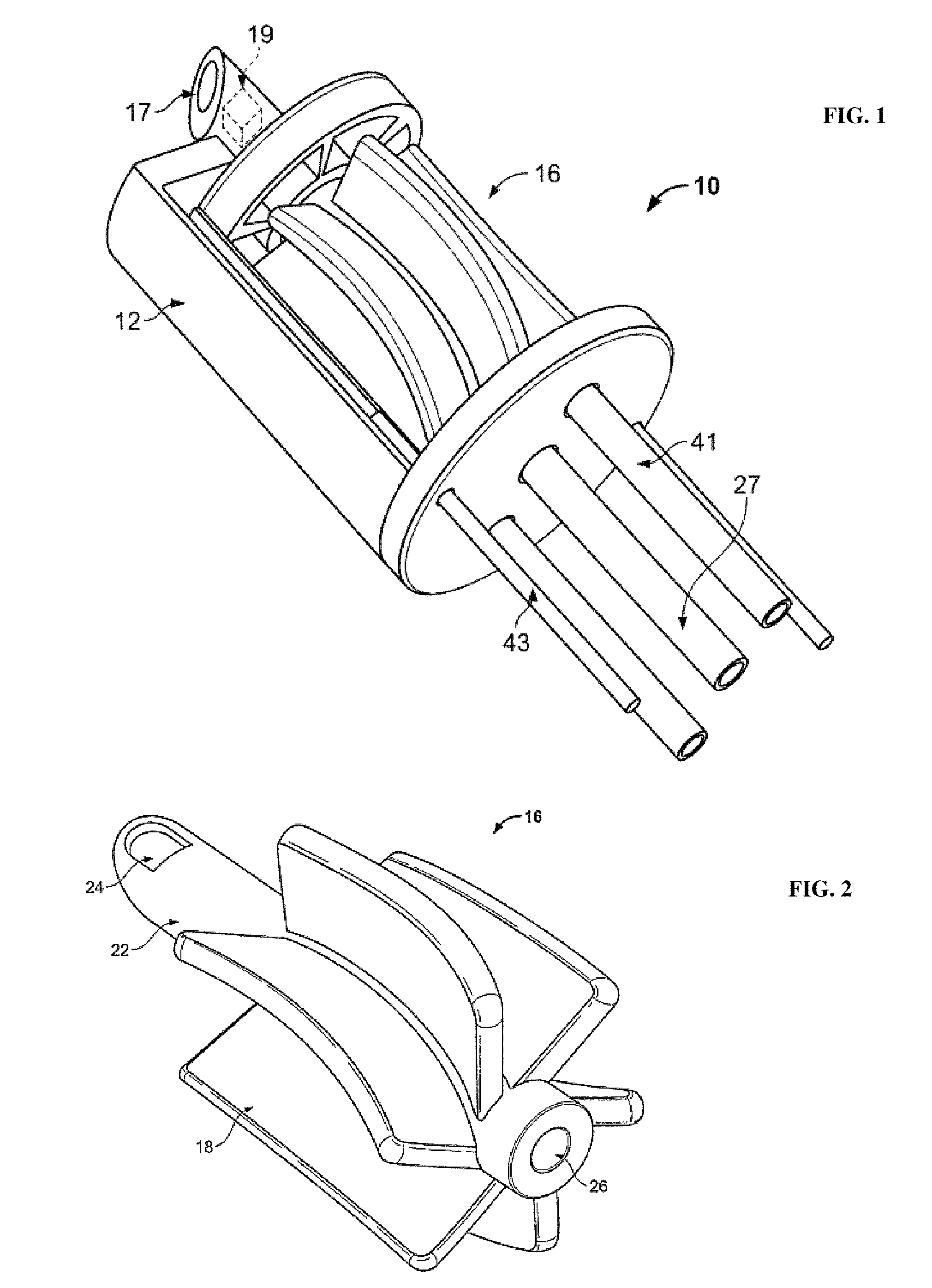
[0036]An alternative embodiment of the turbine member 16 is illustrated in FIG. 7. The principal difference between the turbine member illustrated in FIGS. 1-5 is that there is a space in between the focusing element 19 and the conduit 27. The space may be an air space or an optical gap providing for the optical energy permission to expand before being focused by the focusing element. In this embodiment, the focusing element 19 and the reflecting material 17 both rotate about the axis by the axle 22, by being substantially connected to the axle by optical glue, or the like. Also, the curved or helical pitch of the turbine vanes 18 is greater than that depicted in FIGS. 1-5, such that they subtend approximately a 90 degree arc about the circumference of the axle 22.

second embodiment

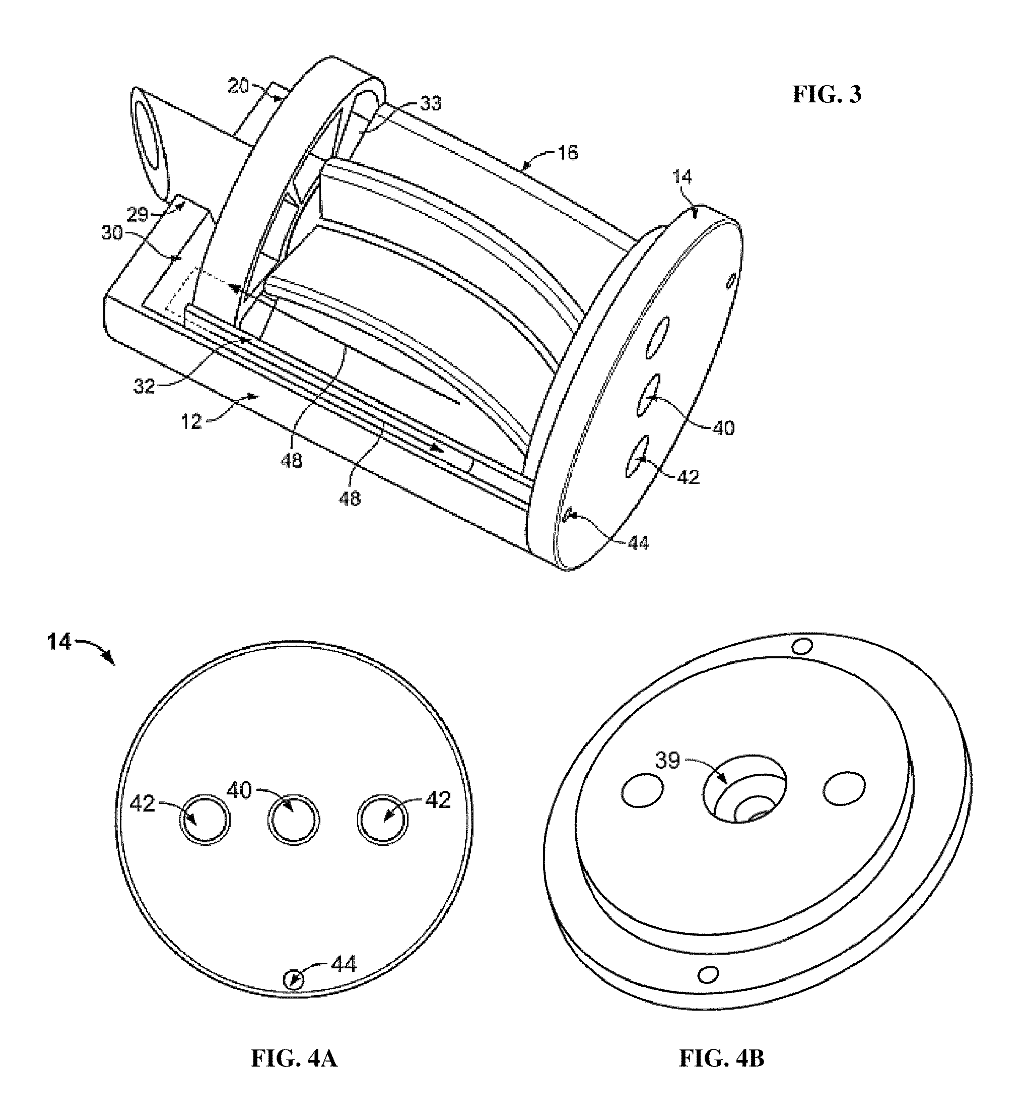
[0037]a cap member 20 is depicted in FIG. 8, and is synonymously termed second cap member 60. The second cap member 60 includes a central opening 64, a collection channel 65 and a plurality of outflow ports 66. The central opening 64 is concentrically mounted onto the distal end of the axle 22 to permit axle 22 to rotate freely thereabout. The collection channel 65 is connected to the outflow ports 66, to permit the outflow of fluid. The outflow ports are substantially aligned with the outflow ports 66 of the catheter cap 14, to allow the outflow to return to the fluid source (not shown). Second cap member 60 is similar to second cap member 60, in that it has an inner annular member 64 through which the axle 22 of turbine member, and an outer annular member 62 which is in concentrically spaced apart relationship therewith 16 passes except that after fluid flows through the spaces 35 it enters a return path by passing through outlet flow ports 66 which are provided about a peripheral...


PUM


Abstract

The present invention relates to a rotating catheter tip for optical coherence tomography based on the use of an optical fiber that does not rotate, that is enclosed in a catheter, which has a tip rotates under the influence of a fluid drive system to redirect light from the fiber to a surrounding vessel and the light reflected or backscattered from the vessel back to the optical fiber.

Description

CROSS-REFERENCE TO RELATED APPLICATIONS[0001]The present application claims priority to U.S. Provisional Patent Application Ser. No. 60 / 728,481, filed Oct. 20, 2005 and is a Continuation-in-Part “CIP” of U.S. patent application Ser. No. 10 / 548,982, which was filed Sep. 7, 2005 and granted a U.S. national stage filing date of May 2, 2006, which claims priority to PCT International Patent Application Serial No. PCT / US2004 / 012773, filed Apr. 23, 2004 and which claims priority to U.S. Provisional Patent Application Ser. No. 60 / 466,215, filed Apr. 28, 2003, all of which are hereby expressly incorporated by reference.BACKGROUND OF THE INVENTION[0002]The present invention relates to catheter probes based on the use of a fiber that does not rotate. More specifically, the present invention relates to optical coherence tomography based on the use of an optical fiber that does not rotate, which is enclosed in a catheter portion.[0003]Myocardial infarction or heart attack remains the leading ca...

Claims


Application Information

Patent Timeline
Patent Type & Authority Patents(United States)
IPC IPC(8): A61B6/00A61B1/05
CPCA61B5/0066A61B5/6852A61B6/12A61B8/4461A61B8/12A61B1/00183A61B5/0084A61B1/3137A61N2007/0091A61M25/0074A61M2202/0476
Inventor MILNER, THOMAS E.FELDMAN, MARC D.OH, JUNG-HWANCHEN, SHAOCHENCASTELLA, PAUL
Owner BOARD OF REGENTS THE TEXAS UNIV SYST
Why Eureka
Try Eureka