Micromachine structure system and method for manufacturing same

a technology of micro-machine structure and manufacturing method, which is applied in the field of micro-mechanical structure system to achieve the effects of improving production yield, high alignment precision, and low cos

Inactive Publication Date: 2010-12-21
PANASONIC CORP
View PDF8 Cites 0 Cited by
  • Summary
  • Abstract
  • Description
  • Claims
  • Application Information

AI Technical Summary

Benefits of technology

[0033]In accordance with a micro-mechanical structure system of the present invention and a production method thereof, a high alignment precision is not required when bonding a movable structure which is formed of a single-crystalline material to a circuit section. This improves the production yield, whereby a micro-mechanical structure system that can be produced at low cost can be provided. Since the variations in the relative distance between and relative positions of a movable structure and an electrode are reduced, a micro-mechanical structure system which allows a movable structure to be driven and controlled with a high precision can be provided.

Problems solved by technology

However, inside a single-crystalline silicon layer, it is difficult to form trenches which are parallel to the single-crystalline silicon layer, and it is impossible by merely processing the single-crystalline silicon layer to realize a hollow shape for allowing a driving electrode and a mirror to oppose each other.

Method used


Image

  • Micromachine structure system and method for manufacturing same
  • Micromachine structure system and method for manufacturing same
  • Micromachine structure system and method for manufacturing same

Examples


embodiment 1

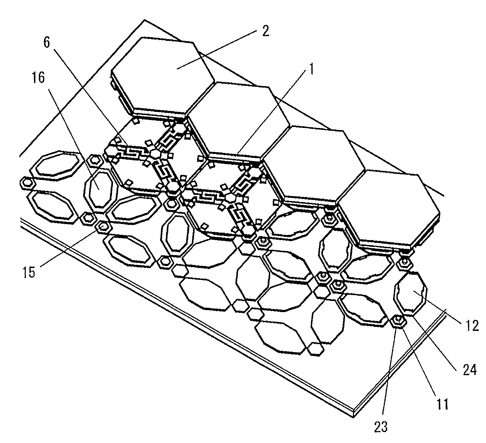
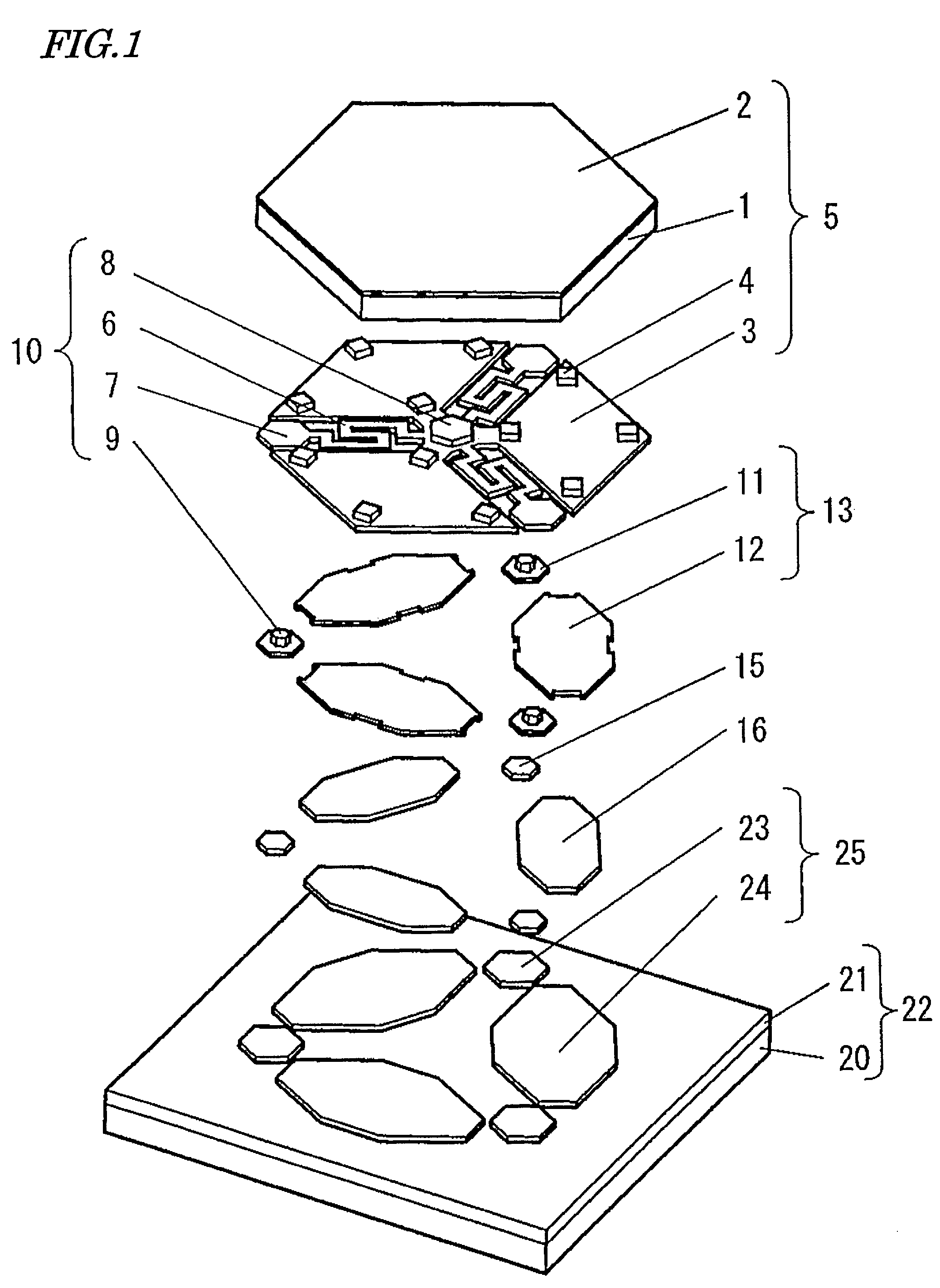
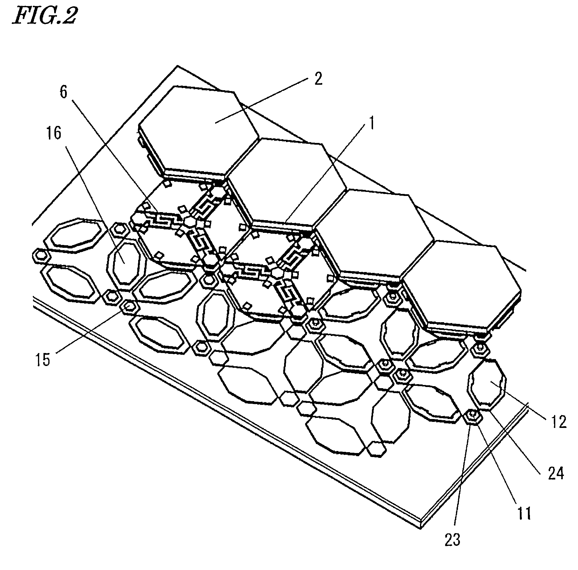
[0114]With reference to FIG. 1, a first embodiment of a mechanical structure system (micromirror device) according to the present invention will be described. FIG. 1 is an exploded perspective view of a micro-mechanical structure system (micromirror device) according to the present embodiment. Although one mirror is illustrated in FIG. 1, the micromirror device of the present embodiment includes a plurality of mirrors in a two-dimensional array.

[0115]The micro-mechanical structure system according to the present embodiment includes: a movable structure 5 at least a portion of which is formed of a single-crystalline material; an elastic supporting member 10 supporting the movable structure 5; a stationary electrode section 13, 25 at least partially opposing the movable structure 5; and a base 22 having a circuit section and having the stationary electrode section 13, 25 affixed thereto.

[0116]The present embodiment is characterized in that the stationary electrode section 13, 25 inclu...

embodiment 2

[0183]FIG. 12 is an exploded perspective view of a micro-mechanical structure system (micromirror device) according to Embodiment 2 of the present invention. In FIG. 12, component elements which are identical to those in Embodiment 1 will be denoted by the same numerals, and the descriptions thereof will be omitted.

[0184]As shown in FIG. 12, intermediate electrodes 70 are formed of polysilicon so as to be coplanar with the hinge members 6. The intermediate electrodes 70 are plate electrodes which are not connected to the hinge members 6 and will not be displaced even when the hinge members 6 are deformed. Electrode bonding portions 71 are formed of polysilicon, and are bonded to the second circuit electrodes 24 by way of the second adhesion members 16. Second link portions 72 are formed of polysilicon, and allow the intermediate electrodes 70 to be linked to the electrode bonding portions 71 in an electrically conducting manner. Second link portions 72 transmit control signals gener...

embodiment 3

[0199]FIG. 15 is an exploded perspective view of a micro-mechanical structure system according to Embodiment 3 of the present invention. As shown in FIG. 15, component elements which are identical to those in Embodiments 1 to 2 will be denoted by the same numerals, and the descriptions thereof will be omitted.

[0200]As shown in FIG. 15, hinge posts 84 are formed at the outer peripheral ends of the hinge members 6, so as to be perpendicular to the hinge members 6. The hinge posts 84 are coupled to the end portions of the hinge electrodes 11, so as to support the hinge members 6. The hinge electrodes 11, the hinge posts 84, the hinge members 6, and the mirror link post 8 are formed integrally, as will be described later.

[0201]A stopper 85 is a plate member which is provided by expanding a portion of the electrode pattern of the second circuit electrodes 24 on the surface of the base 22. When the movable structure 5 has pivoted to a large extent, the stopper 85 comes in contact with an ...


PUM


Abstract

A micro-mechanical structure system according to the present invention includes: a movable structure 5, at least a portion of the movable structure 5 being formed of a single-crystalline material; an elastic supporting member 10 for supporting the movable structure 5; a stationary electrode section 13, 25 at least partially opposing the movable structure 5; and a base 22 which has a circuit section and to which the stationary electrode 13, 25 is affixed. The stationary electrode section 13, 25 includes a first electrode layer (upper stationary electrode layer) 13 positioned relative to the movable structure 5 and a second electrode layer (lower stationary electrode layer) 25 positioned relative to the base 22, the first electrode layer 13 and the second electrode layer 25 being bonded to each other via adhesion layers 15 and 16.

Description

TECHNICAL FIELD[0001]The present invention relates to a micro-mechanical structure system for driving a minute movable section which is supported by an elastic supporting member, and relates in particular to: a micro-mechanical structure system which is suitable for a micromirror whose movable section has a light reflecting surface, and a micromirror device including a two-dimensional array of such micromirrors so as to be capable of independent driving; and a production method thereof.BACKGROUND ART[0002]In recent years, very small micromirror devices utilizing MEMS (Micro Electro Mechanical System) technology have been proposed, with a view to controlling the wavefront of light in the field of adaptive optics, and realizing a mechanical optical switch for reflecting a light beam in such a manner as to enter a photoelectric element or an optical fiber which is at a predetermined position.[0003]In a micromirror device, it is necessary to enhance the planarity of the mirror surface i...

Claims


Application Information

Patent Timeline
Patent Type & Authority Patents(United States)
IPC IPC(8): G02B26/00
CPCG02B1/02G02B26/0841
Inventor KAJINO, OSAMUTOMITA, HIRONORIMUSHIKA, YOSHIHIRO
Owner PANASONIC CORP
Why Eureka
Try Eureka