Fiber optic strain gage and carrier

a fiber optic strain and carrier technology, applied in the direction of optical apparatus testing, force measurement by measuring optical property variation, instruments, etc., can solve the problems of loss of measurement accuracy, loss of sensitivity, etc., and achieves low resistance to strain, quick and easy attachment, and no undesirable loss of gage performance

Active Publication Date: 2010-12-28
LUNA INNOVATIONS
View PDF54 Cites 22 Cited by
  • Summary
  • Abstract
  • Description
  • Claims
  • Application Information

AI Technical Summary

Benefits of technology

[0010]The present invention provides a fiber optic strain gage having the benefits of a pre-mounted strain gage without undesirable loss of gage performance. The gage is quickly and easily attached to a test specimen. The gage comprise a carrier having a passageway for receiving a continuous length of optical fiber containing a fiber Bragg grating (FBG) and means for fastening the carrier to the test specimen. The carrier is made of a flexible plastic that can be attached to the test specimen, for example using adhesive. The gage carrier is compliant and provides very little resistance to strain along the axis of measurement; therefore, the test specimen does not have to work against the stiffness of the carrier.
[0013]An optical fiber containing one or more fiber FBGs is the active strain sensing transducer in the gages herein. The gage carrier serves several important purposes in facilitating the use of an optical FBG as a strain gage. The gage carrier serves as a fiber holding fixture providing a packaged device that is easily handled. The gage carrier provides protection to the fiber during installation and while it is in use. The gage carrier also provides features that allow quick and reliable attachment to the test specimen. An additional aspect of this invention is a FBG strain gage exhibiting the accuracy and sensitivity of gages that are not pre-mounted to a carrier, while providing the convenience of a pre-mounted gage.

Problems solved by technology

Although the use of a carrier for such gages significantly improves handling and mounting, its use can also degrade gage performance.
This can result in a loss of sensitivity.
Distortion of the carrier other than by pure linear strain can result in loss of accuracy of measurement because the sensing element is not exposed to the true strain present in the test specimen.

Method used


Image

  • Fiber optic strain gage and carrier
  • Fiber optic strain gage and carrier
  • Fiber optic strain gage and carrier

Examples


Embodiment Construction

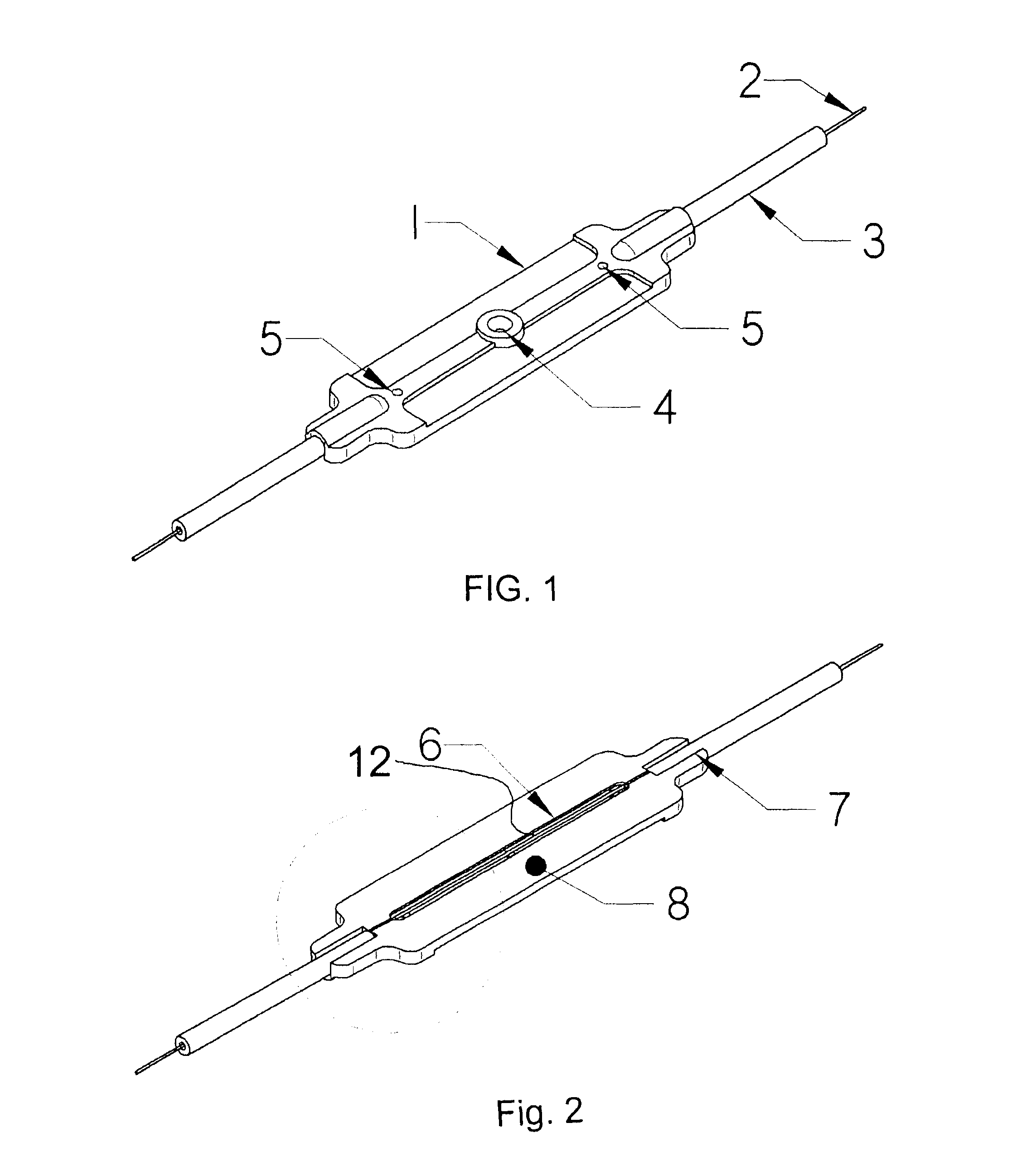
[0024]The invention is further described by reference to the Drawings where like features are referenced by the same numbers.

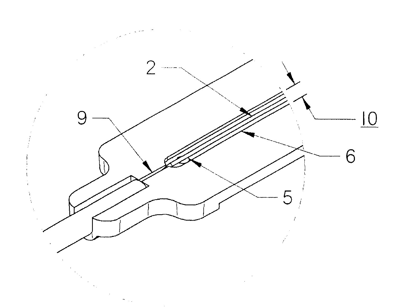
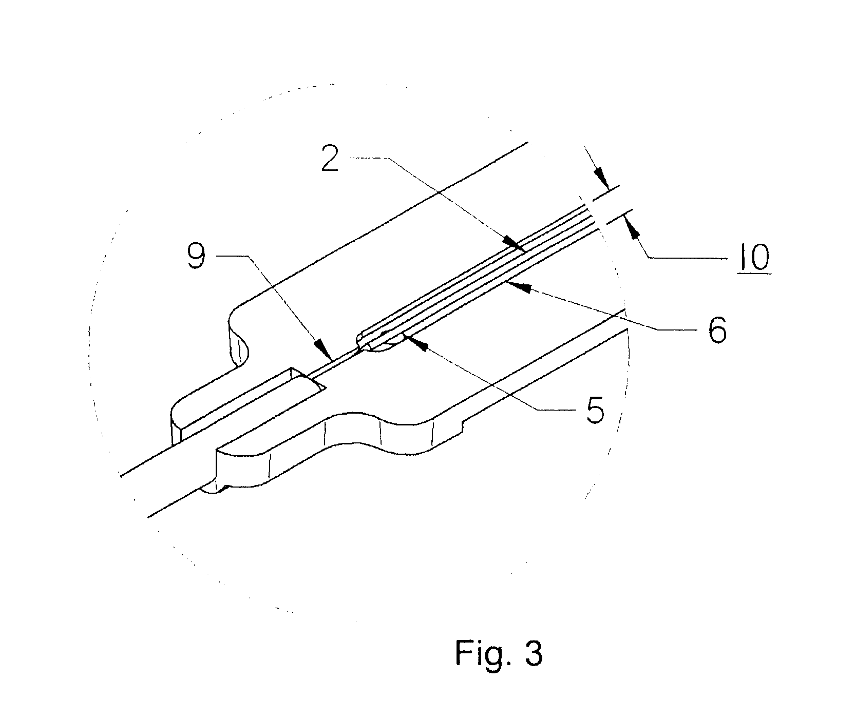
[0025]FIGS. 1-4 illustrate an exemplary embodiment of a carrier mounted FBG strain gage of the present invention. The exemplary gage consists of a gage carrier 1 which holds and supports an optical fiber 2 containing a fiber Bragg grating (12) prior to installation. Optional, buffer tubes 3 protect fiber extending from the ends of the carrier during installation and use. A means for fastening the carrier to a test specimen is provided on surface 8. This fastening means can be selected to allow selective removal of the carrier to allow for repositioning of the carrier during installation or for optional removal of the carrier after bonding of the fiber. The carrier may be attached to the test specimen using epoxy, adhesives, clamps, screws or other fastening techniques. In a preferred embodiment, the carrier is attached to the test specimen using an adhesive tr...


PUM

PropertyMeasurementUnit
lengthaaaaaaaaaa
depthaaaaaaaaaa
widthaaaaaaaaaa

Abstract

The current invention relates to optical gages designed to measure strain on the surface of a test specimen. The gages of this invention is designed to be installed and used in a manner similar to conventional electronic foil strain gages, but to have the advantages of an all-optical gage. The gage of this invention is constructed to allow surface strain on the test specimen to be transferred to a length of optical fiber containing a fiber Bragg grating (FBG). As strain is applied to the fiber, the optical spectrum center wavelength reflected by the Bragg grating shifts in wavelength. This shift in wavelength can be converted directly to units of strain. The current invention provides a gage carrier design for use with fiber optic strain sensors comprising one or more FBGs which provide the benefits of a carrier for ease of handling and mounting without degrading gage performance. The gage carrier provides features that allow the FBG to be precisely positioned and securely bonded to the test specimen in a controlled manner. The carrier additionally provides fiber protection to the installed FBG.

Description

BACKGROUND OF THE INVENTION[0001]In the past few years, fiber optic-based strain gages have gained acceptance in the market as an alternative to conventional electronic gages which are based, for example, on changes in electrical resistance, inductance or capacitance. In many applications, such as civil structure monitoring, down-hole oil and gas applications, as well as marine, and aerospace applications, fiber optic gages offer several advantages over conventional gages. Unlike electronic gages, fiber-based gages are not sensitive to electromagnetic interference and are well suited for use in electrically-noisy environments. Fiber-based gages are also readily multiplexed, allowing many gages to operate on a single fiber over long distances. Fiber-based gages can be made very small and lightweight for use in confined spaces. Fiber-based gages can also be made to withstand high temperature and corrosive environments.[0002]A wide variety of optical gages are available that utilize va...

Claims


Application Information

Patent Timeline
Patent Type & Authority Patents(United States)
IPC IPC(8): G01L1/24G02B6/00
CPCG01B11/18G01L1/246G01M11/085
Inventor FERGUSON, STEPHEN K.
Owner LUNA INNOVATIONS
Why Eureka
Try Eureka