Tool manipulator especially for onshore and offshore drilling platforms

a tool and platform technology, applied in the direction of manual control with multiple control members, mechanical control devices, fluid removal, etc., can solve the problems of reducing the space above the wellbore, occupying relatively much space, and the entire crane structure occupied relatively much space, so as to reduce the burden of inspection, maintenance and replacement, and be easily adaptable to many different uses, applications or installations.

Inactive Publication Date: 2010-12-28
BLOHM VOSS REPAIR
View PDF8 Cites 2 Cited by
  • Summary
  • Abstract
  • Description
  • Claims
  • Application Information

AI Technical Summary

Benefits of technology

[0007]In view of the above, it is an object of the invention to provide a manipulator apparatus for carrying and manipulating a tool, especially for an onshore or offshore drilling platform, whereby the manipulator apparatus has a compact structural size and a reduced complexity compared to the prior art due to a simplified construction and a reduced number of total parts. It is a further object of the invention to provide such a manipulator that carries the tool or tools with simple linear movements, while omitting articulated joints from the manipulator apparatus, and while avoiding pivoting or swinging motions during the manipulation. A further object of the invention is to achieve a maintenance-free operation due to a simple robust structure of the manipulator apparatus. The invention further aims to avoid or overcome the disadvantages of the prior art, and to achieve additional advantages as apparent from the present specification. The attainment of these objects is, however, not a required limitation of the presently claimed invention.
[0011]With the above described construction, it is possible to achieve a very robust and simple structural arrangement of the manipulator apparatus, using only standardized components of steel construction, for example readily available steel I-beams and U-beams, hydraulic cylinders, connections bolts, bearing blocks, etc. Furthermore, the moveable bearing support of the column elements relative to one another and the work arm elements relative to one another is achieved simply by the mutual sliding support of oppositely lying surfaces of the column elements on each other, and of the work arm elements on each other, respectively forming slide bearings which may further be fitted with low-friction plastic (e.g. polytetrafluoroethylene) slide bearing surfaces. Namely, the web of the H-profile member slides supportedly between the webs of the U-profile members, while the flanges of the H-profile member slide outwardly along the flanges of the U-profile members with the U-profile members constrained between the flanges of the H-profile members i.e. within the profile of the H-profile member.
[0012]This overall structural arrangement achieves a very economical construction as well as an efficient utilization of the structural space without tying up a lot of space around or above the wellbore on the drilling platform. A further preferred feature of the invention provides that at least one hydraulic cylinder is arranged and received within each U-profile member, to ensure a very compact construction as well as a protected installation space for the hydraulic cylinder.
[0014]In a further preferred embodiment of the invention, the hydraulic oil supply to the hydraulic cylinders is provided through fixedly installed hydraulic pipes from a hydraulic manifold arrangement, while preferably completely avoiding the use of flexible hydraulic hoses in the manipulator apparatus. Thereby, the hydraulic adjustment of the variable extension of the column and the work arm can be efficiently and precisely carried out, without hydraulic losses and lack of positioning precision due to flexing or expansion of such hydraulic hoses under pressure. Avoiding hoses also greatly reduces the inspection, maintenance and replacement work burden. This arrangement also ensures that the manipulator apparatus is a versatile, self-contained unit that is easily adaptable to many different uses, applications or installations. It is simply necessary to connect an external, controlled hydraulic oil supply to respective hydraulic supply manifolds of the column and the work arm.

Problems solved by technology

Because the drillpipes, couplings and other components are sizeable and heavy, these operations are carried out with correspondingly heavy and sizeable clamping tools, screwing tools, and the like generally known in the field of well drilling.
Thereby the space above the wellbore is drastically limited because the crane and cable equipment must be positioned directly above the wellbore.
Furthermore, the entire crane structure takes up relatively much space, especially in the height direction above the wellbore.
Another problem with the known cable crane suspension of the drillpipe connecting tools is that the suspension cable does not provide a fixed rigid positioning of the tools, but rather any suspended tool may start swinging or oscillating on the cable.
Such an unstable position of the tool makes it difficult to bring the tool into the exactly proper position for carrying out its work.
Such rail-guided systems are rather complex, suffer a further disadvantage of being inflexible and not adaptable to various applications, and also encroach on the space around the wellbore due to the guide rails mounted on the drilling platform floor, for example.

Method used


Image

  • Tool manipulator especially for onshore and offshore drilling platforms
  • Tool manipulator especially for onshore and offshore drilling platforms

Examples


Embodiment Construction

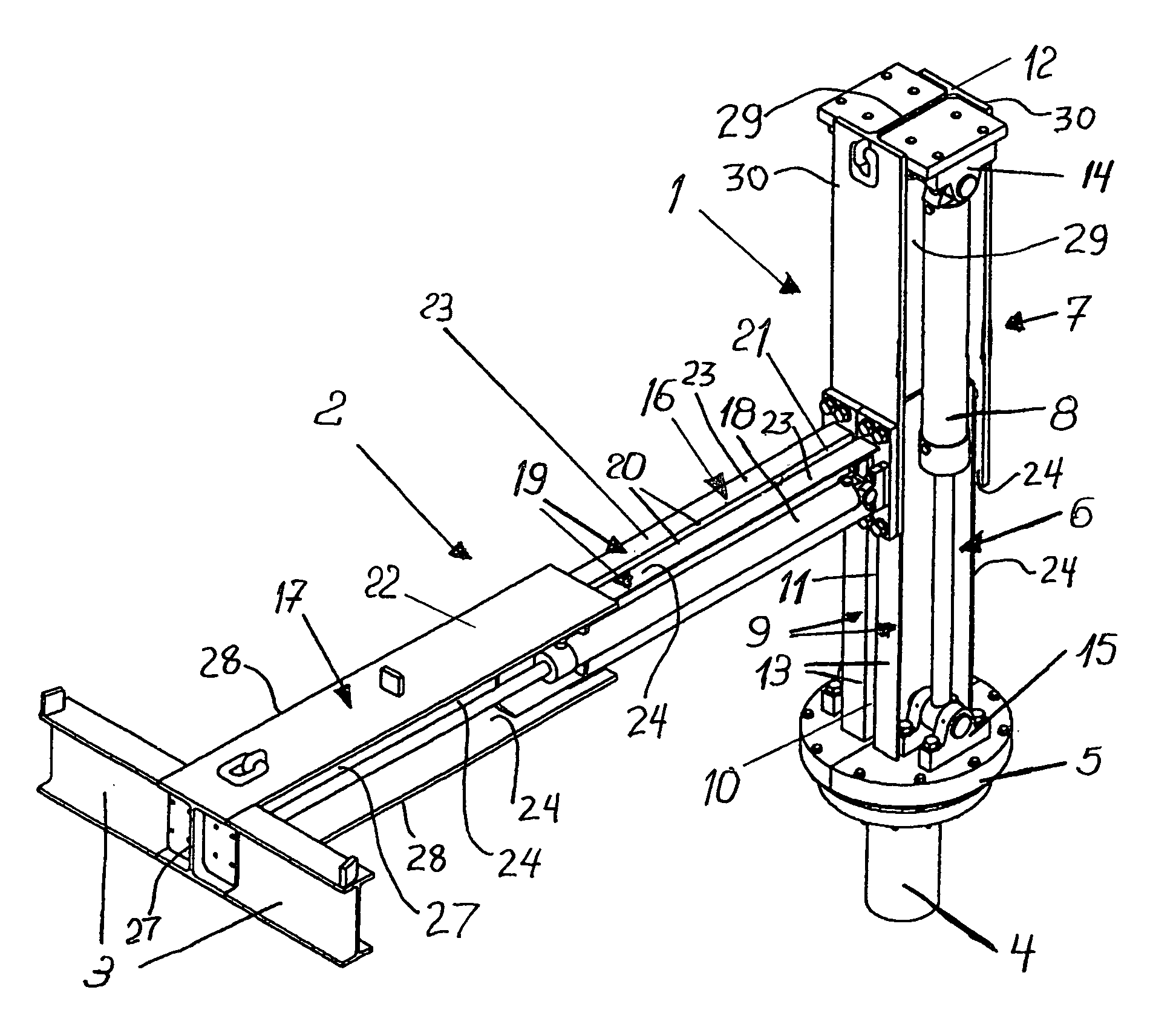
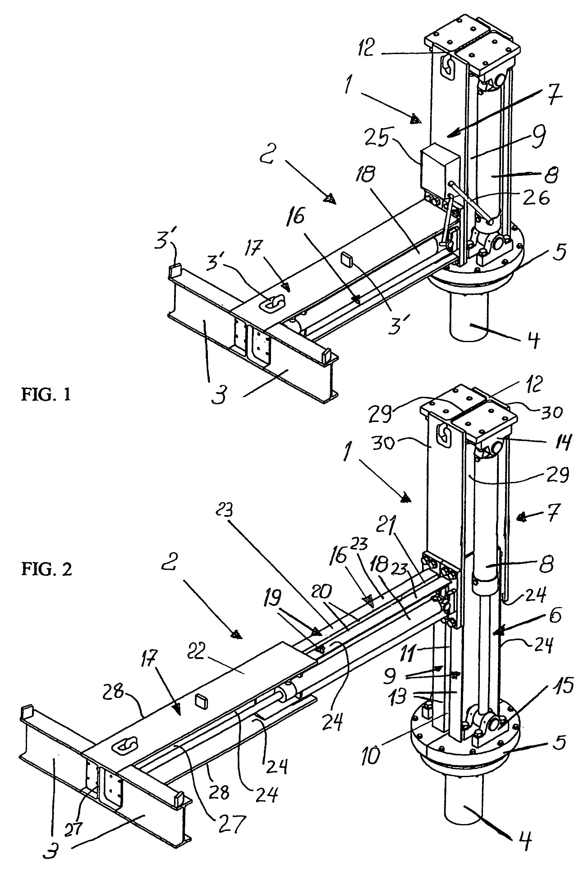
[0018]As shown in FIGS. 1 and 2, the illustrated example embodiment of a manipulator apparatus according to the invention includes a height adjustable vertical column 1 and a variably extendable horizontal work arm 2 carried by the column 1. The distal free end of the work arm 2 carries a tool receiver 3 adapted to carry the desired drillstring connection tool or tools such as clamping and screwing tools for connecting drill pipes to the drillstring in a wellbore being drilled from an onshore or offshore drilling platform. The particular tools are not shown but are well known in the pertinent art. The tool receiver 3 may be any suitable support structure for carrying the intended tools. In the illustrated example embodiment, the receiver 3 is simply a transversely extending I-beam as a transverse yoke beam with suitable tool receiver fittings 3′ such as mounting lugs, mounting holes, lifting or tie-down rings, and the like. The receiver 3, the work arm 2 and the column 1 are prefera...


PUM


Abstract

A manipulator apparatus carries tools for connecting drillpipes to the drillstring in a wellbore on a drilling platform. A telescopically extendable horizontal work arm is carried on a telescopically extendable vertical column, and the tools are to be mounted on a free end of the work arm. The column is manually rotatable about a vertical axis. The column and the work arm are each respectively formed of a fixed element and a telescopically extendable element. The fixed element is preferably formed of two U-profile members arranged back-to-back, and the extendable element includes an H-profile member with its web received between the webs of the two U-profile members. This forms a telescopic slide bearing of the H-profile member sliding along the two U-profile members. The hydraulic cylinders are received in the recessed spaces of the profile members.

Description

PRIORITY CLAIM[0001]This application is based on and claims the priority under 35 U.S.C. §119 of German Patent Applications 10 2008 022 134.1, filed on Apr. 30, 2008 and 10 2008 060 835.1, filed on Dec. 5, 2008, the entire disclosures of which are incorporated herein by reference.FIELD OF THE INVENTION[0002]The invention relates to a manipulator for carrying and positioning tools, especially controllable screwing and clamping tools, in relation to drillpipes for drilling a wellbore on an onshore or offshore well drilling platform.BACKGROUND INFORMATION[0003]For drilling a wellbore from an onshore or offshore drilling platform, for example for an oil well or natural gas well, a plurality of drillpipes are connected together in succession to form a drillstring carrying the drilling bit progressively deeper into the wellbore being drilled. The individual drillpipe sections or strands are screwed together via screw threadings at their ends, sometimes additionally using threaded coupling...

Claims


Application Information

Patent Timeline
Patent Type & Authority Patents(United States)
IPC IPC(8): E21B19/00B66C23/18B25J17/02B25J18/00
CPCE21B19/00Y10T74/20305
Inventor GROTHERR, JOERNRUEGER, NILS
Owner BLOHM VOSS REPAIR
Why Eureka
Try Eureka