Digital baseband system

a digital baseband and digital baseband technology, applied in the field of communication systems, can solve the problems of low addressability and allocation flexibility, rate-conversion delay, rate-conversion logic overhead and power consumption, etc., and achieve the effect of reducing power consumption and efficient gate coun

Active Publication Date: 2010-12-28
IBM CORP
View PDF31 Cites 6 Cited by
  • Summary
  • Abstract
  • Description
  • Claims
  • Application Information

AI Technical Summary

Benefits of technology

[0010]The invention provides a baseband system for a short-range radio communication system. It is conform to the Bluetooth baseband specification and is well-suited for an efficient hardware implementation, providing a low-power, small-sized, and low-cost radio subsystem design. The baseband system comprises a transceiver unit and a buffer unit, whereby the system has an efficient gate count and a reduced power consumption.
[0011]The design of a transceiver unit is based on a pipelined signal processing with distributed data path flow control. The transceiver unit processes outgoing and incoming packets, and comprises a plurality of signal processing units connected in sequence, whereby each signal processing unit is clocked by a common clock signal. A mode line is connected to each signal processing unit for switching each signal processing unit between a transmit mode and a receive mode. A control line to which each signal processing unit is connected communicates flow control information either in the transmit mode to one or more of the preceding signal processing units or in the receive mode to one or more of the following signal processing units. The described device can also be implemented as a transmitter or receiver only, whereby then the mode line can be omitted.
[0012]The buffer unit comprises a buffer system that applies a flexible memory organization concept, which leads to an efficient implementation of buffers or storage elements in terms of gate count and power consumption, and offers the flexib

Problems solved by technology

Known disadvantages of current implementations of digital baseband systems based on rate-conversion between successive signal processing modules are the rate-conversion delay, the rate-conversion

Method used


Image

  • Digital baseband system
  • Digital baseband system
  • Digital baseband system

Examples


Embodiment Construction

[0036]Although the present invention is applicable in a broad variety of communication systems it will be described with the focus put on an embodiment to a short-range radio communication system that conforms to the Bluetooth baseband specification. In the figures, same reference numerals are used to denote the same or like parts.

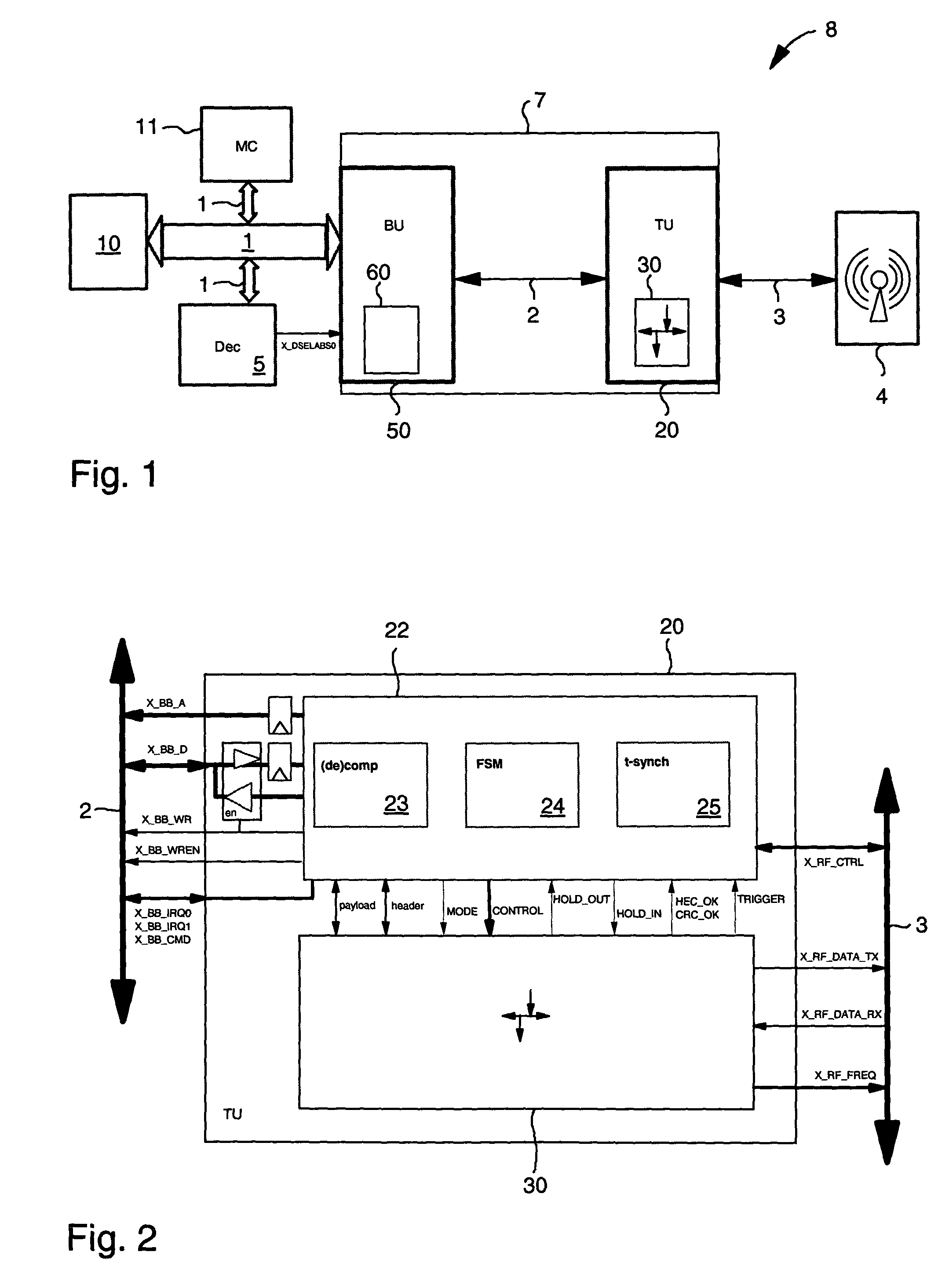
[0037]FIG. 1 illustrates mapping of a baseband architecture onto a hardware / firmware platform that implements a baseband system 8 of the short-range radio communication system. A link manager and link controller, which for the sake of clarity are not shown in the figure, are implemented in firmware. Code is executed on a real-time operating system on an embedded microcontroller 11 that is interconnected via a system bus 1 with a bus decoder 5, and not shown devices, such as memory devices, bus arbiter, interrupt controller, timers, and external interfaces. The embedded microcontroller 11 can be an ARM7TDMI microcontroller. An AMBA advanced system bus (ASB)...


PUM


Abstract

Communication device for processing outgoing and incoming packets. The device includes a plurality of signal processing units connected in sequence, each signal processing unit being clocked by a common clock signal. The device further includes a mode line connected to each signal processing unit for switching each signal processing unit between a transmit mode and a receive mode. The device further includes a control line to which each signal processing unit is connected. The control line communicating flow control information either in the transmit mode to at least one of the preceding signal processing units or in the receive mode to at least one of the following signal processing units.

Description

TECHNICAL FIELD AND BACKGROUND OF THE INVENTION[0001]The present invention relates to a communication system for processing outgoing and incoming data. More particularly the invention relates to a baseband unit for handling packets comprising a header and payload.[0002]Although the present invention is applicable in a broad variety of communication systems it will be described with the focus put on an application to a short-range radio communication system that conforms to the Bluetooth baseband specification, as can be found in “Specification of the Bluetooth System”, Version 1.0 B, Bluetooth Special Interest Group (SIG), Dec. 1, 1999.[0003]The intensified wish to connect a wide range of computing and telecommunications devices easily and simply, without the need to buy, carry, or connect cables, has been realized by several companies. The Bluetooth Special Interest Group (SIG) and the IEEE Wireless Personal Area Network (WPAN) standardization group 802.15 are working on a specific...

Claims


Application Information

Patent Timeline
IPC IPC(8): H04L7/00H04L23/00H04L12/26H04L12/56H04L12/28
CPCH04W88/02H04W84/10H04W84/18H04W52/0229Y02B60/50Y02D30/70H04L25/00
Inventor FURRER, SIMEONMAIWALD, DIETRICHSCHOTT, WOLFGANG H.
Owner IBM CORP
Why Eureka
Try Eureka