Density-matched polymer slurries

a density-matched polymer and slurry technology, which is applied in the direction of papermaking, textiles and papermaking, polishing compositions, etc., can solve the problems of reducing the drag reduction efficiency of the polymer, the inability to place the pao in the hydrocarbon, and the specialized injection equipment of drag reducing gels

Active Publication Date: 2011-01-04
BAKER HUGHES INC
View PDF35 Cites 0 Cited by
  • Summary
  • Abstract
  • Description
  • Claims
  • Application Information

AI Technical Summary

Benefits of technology

[0008]Another object of the invention is to continuously produce a polymer DRA product that can be readily transported and introduced into a hydrocarbon fluid without the need for equipment more specialized than that presently being used.
[0009]In carrying out these and other objects of the invention, there is provided, in one form, a density-matched particle slurry that includes a carrier liquid and a plurality of core particles within the carrier liquid. The core particles further include a density-matching material on the surfaces of the core particles where a majority of the density-matched core particles bearing the density-matching materials to have a combined density substantially equal to that of the carrier liquid. The density-matching may be located upon, adherent to, affixed upon or otherwise connected to the core particle surfaces. By “substantially equal to” is meant that the densities are sufficiently the same to improve the stability of the slurry. As will be discussed, as a practical matter it is close to impossible to exactly match the combined density of all of the particles bearing the density-matching materials with the carrier liquid, such as over a broad temperature range or over an ambient temperature range, but substantial improvement may be achieved.

Problems solved by technology

A problem generally experienced with simply grinding the polyalpha-olefins (PAOs) is that the particles will “cold flow” or stick together after the passage of time, thus making it impossible to place the PAO in the hydrocarbon where drag is to be reduced, in a form of suitable surface area, and thus particle size, that will dissolve or otherwise mix with the hydrocarbon in an efficient manner.
Further, the grinding process or mechanical work employed in size reduction tends to degrade the polymer, thereby reducing the drag reduction efficiency of the polymer.
However, these drag reducing gels also typically demand specialized injection equipment, as well as pressurized delivery systems.
The gels or the solution DRAs are unstable with regard to quality and have a defined set of conditions that have to be met by mechanical equipment to pump them, including, but not necessarily limited to viscosity, vapor pressure, undesirable degradation due to shear, etc.
The gel or solution DRAs are also limited to about 10% polymer as a maximum concentration in a carrier fluid due to the high solution viscosity of these DRAs.
Thus, transportation costs of some conventional DRAs are considerable, since up to about 90% of the volume being transported and handled is inert material.
Yet none of these prior methods has proven entirely satisfactory.

Method used


Image

  • Density-matched polymer slurries
  • Density-matched polymer slurries
  • Density-matched polymer slurries

Examples


example 1

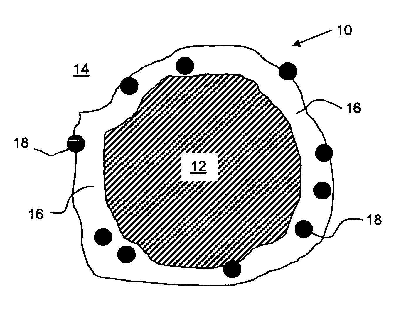
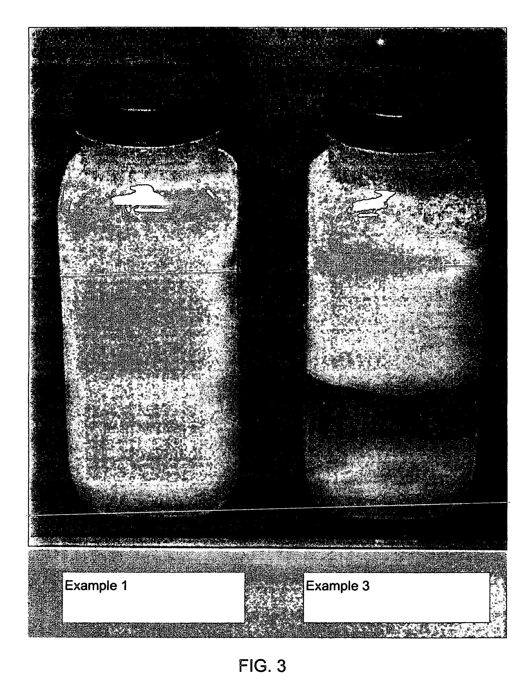
[0035]A 2 g sample of Ritapeg 150DS (polyethylene oxide 150 distearate ester, or “wax,” from Rita Corporation) was added to 58 g Dowanol PnB (propylene glycol n-butyl ether, from Dow Chemical) and heated to 120° F. (49° C.) to dissolve the wax. Separately, 19.9 g of Microthene F (polyethylene copolymer, average particle size 25 μm, from Equistar) was added to 100 g Dowanol PnB. A 100 g quantity of precipitated polyalpha-olefin (PAO) polymer (as a wet cake containing residual glycol, stearate salts, etc.) was added to the Microthene slurry under high shear at ambient temperature. The shear was provided by a 1″ (2.54 cm) Cowels blade run at 2000 rpm for 5 min. The wax solution was added secondarily to the polymer slurry under high shear. The mixture was allowed to stand and cool to ambient temperature for one hour. The resulting slurry had a water-like viscosity and showed no signs of separation after sitting unagitated for 7 months. The slurry was observed to dissolve rapidly in hexa...

example 2

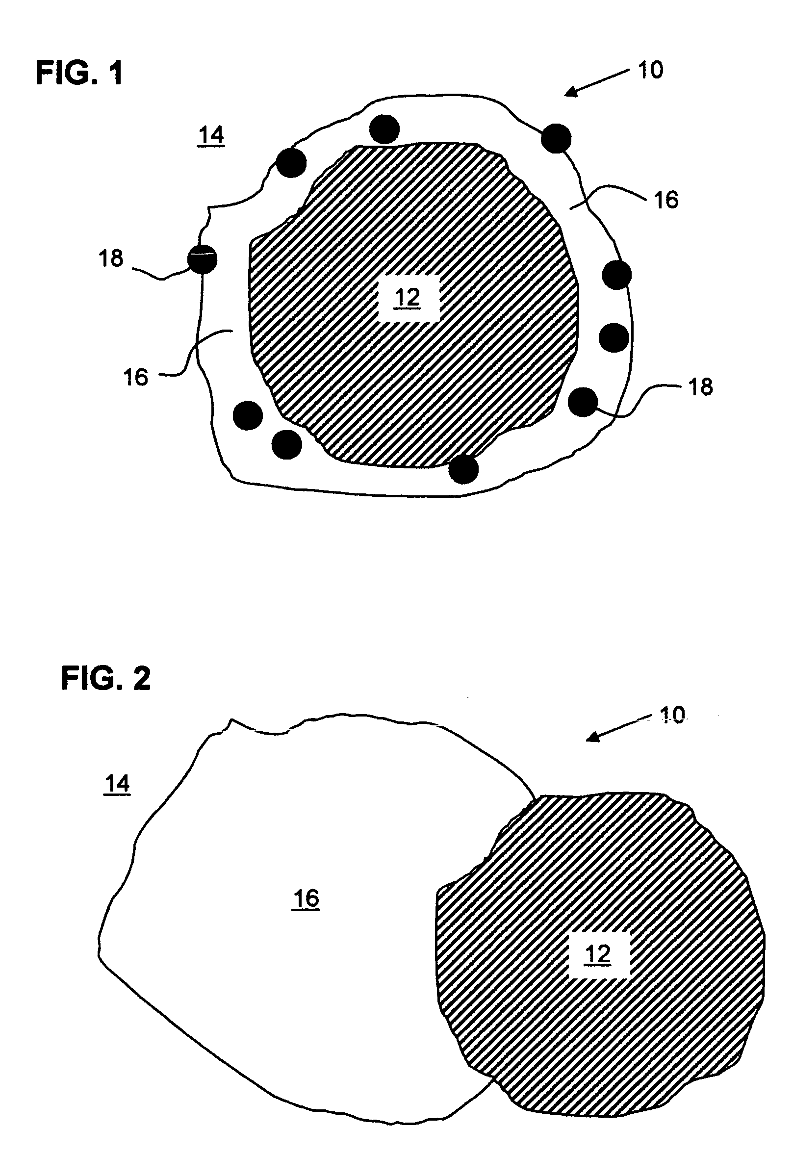
[0036]A similar preparation method as Example 1 was prepared with the omission of the Microthene (particulate) component. The resulting slurry was unstable and separated overnight, giving a clear lower phase with an opaque upper layer of PAO polymer.

example 3

[0037]The same preparation method as Example 1 was prepared with the omission of the Ritapeg 150 DS (wax) component. This slurry separated quickly giving a clear middle layer with a lower layer of white solids (Microthene) and an opaque upper layer of DRA polymer. Examples 1 and 3 are shown in the attached pictures of FIG. 3.


PUM

PropertyMeasurementUnit
temperatureaaaaaaaaaa
mean particle diameteraaaaaaaaaa
temperatureaaaaaaaaaa

Abstract

Polymer slurries of ultrahigh molecular weight polyalpha-olefins are made stable toward settling, separation and agglomeration by surface treatment with a combination of wax and optional relatively high-density particulates. The selection of the surface coating acts not only as an anti-blocking agent, or partitioning aid to keep the tacky polymer particles separated, but also provides the suspended polymer particle with a density that matches the carrier. This prevents separation of the slurry components over time. Such materials, ultimately used as pipeline additives to reduce the fluid drag and increase the volumetric throughput, can be stored and shipped for extended periods of time without degradation of the slurry quality. Upon injection into the pipeline, the polymer particle dissolves quickly, unhindered by the coating.

Description

FIELD OF THE INVENTION[0001]The invention relates to processes for producing and using polymeric drag reducing agents, and most particularly to processes for providing and using polymeric drag reducing agents in a form that is stable during storage, handling and shipping.BACKGROUND OF THE INVENTION[0002]The use of polyalpha-olefins or copolymers thereof to reduce the drag of a hydrocarbon flowing through a conduit, and hence the energy requirements for such fluid hydrocarbon transportation, is well known. These drag reducing agents or DRAs have taken various forms in the past, including slurries or dispersions of ground polymers to form free-flowing and pumpable mixtures in liquid media. A problem generally experienced with simply grinding the polyalpha-olefins (PAOs) is that the particles will “cold flow” or stick together after the passage of time, thus making it impossible to place the PAO in the hydrocarbon where drag is to be reduced, in a form of suitable surface area, and thu...

Claims


Application Information

Patent Timeline
Patent Type & Authority Patents(United States)
IPC IPC(8): C08L91/06C08J3/22C08G73/10C08K3/20C08K5/01C08F2/44
CPCC08J3/11C08L23/04C08L23/0892C08L23/10C08L91/06C08L2666/06
Inventor MARTIN, THOMAS J.CHOU, LU CHIEN
Owner BAKER HUGHES INC
Why Eureka
Try Eureka