Electric power conversion system

a technology of electric power conversion and conversion circuit, which is applied in the direction of electric variable regulation, process and machine control, instruments, etc., can solve the problems of reducing the voltage of capacitors, reducing the efficiency of inverters, and reducing the volume of reverse voltage application circuits, so as to reduce the loss of reverse recovery, and simplify the circuit configuration

Inactive Publication Date: 2011-01-18
KK TOSHIBA
View PDF16 Cites 13 Cited by
  • Summary
  • Abstract
  • Description
  • Claims
  • Application Information

AI Technical Summary

Benefits of technology

[0007]The present invention has been devised in view of such the problems of the preceding technique, and it is an object thereof to provide an electric power conversion system that allows for a reduced reverse recovery loss of a free wheeling diode by a reverse voltage application circuit with a simplified circuit configuration and with low loss.
[0010]According to the present invention, it is enabled to provide an electric power conversion system allowing for a reduced reverse recovery loss of a free wheeling diode by a reverse voltage application circuit with a simplified circuit configuration and with low loss.

Problems solved by technology

Hence much loss is caused at the free wheeling diode by the reverse current and direct current voltage, with a worsened efficiency of the inverter.
However, in the preceding technique, the reverse voltage application circuit has an auxiliary power supply composed of capacitors and diodes, and drives switching devices for reverse voltage application by using the auxiliary power supply, so the configuration of the reverse voltage application circuit is complicated, causing also the volume of the reverse voltage application circuit to be enlarged, as a significant issue.
Further, for capacitors to be charged, currents are conducted through diodes, not simply causing heat to dissipate as losses by those currents at the diodes, but also having the capacitors charged with voltages reduced lower than voltages of low-voltage direct currents by fractions of the losses at the diodes, as an issue.

Method used


Image

  • Electric power conversion system
  • Electric power conversion system
  • Electric power conversion system

Examples


first embodiment

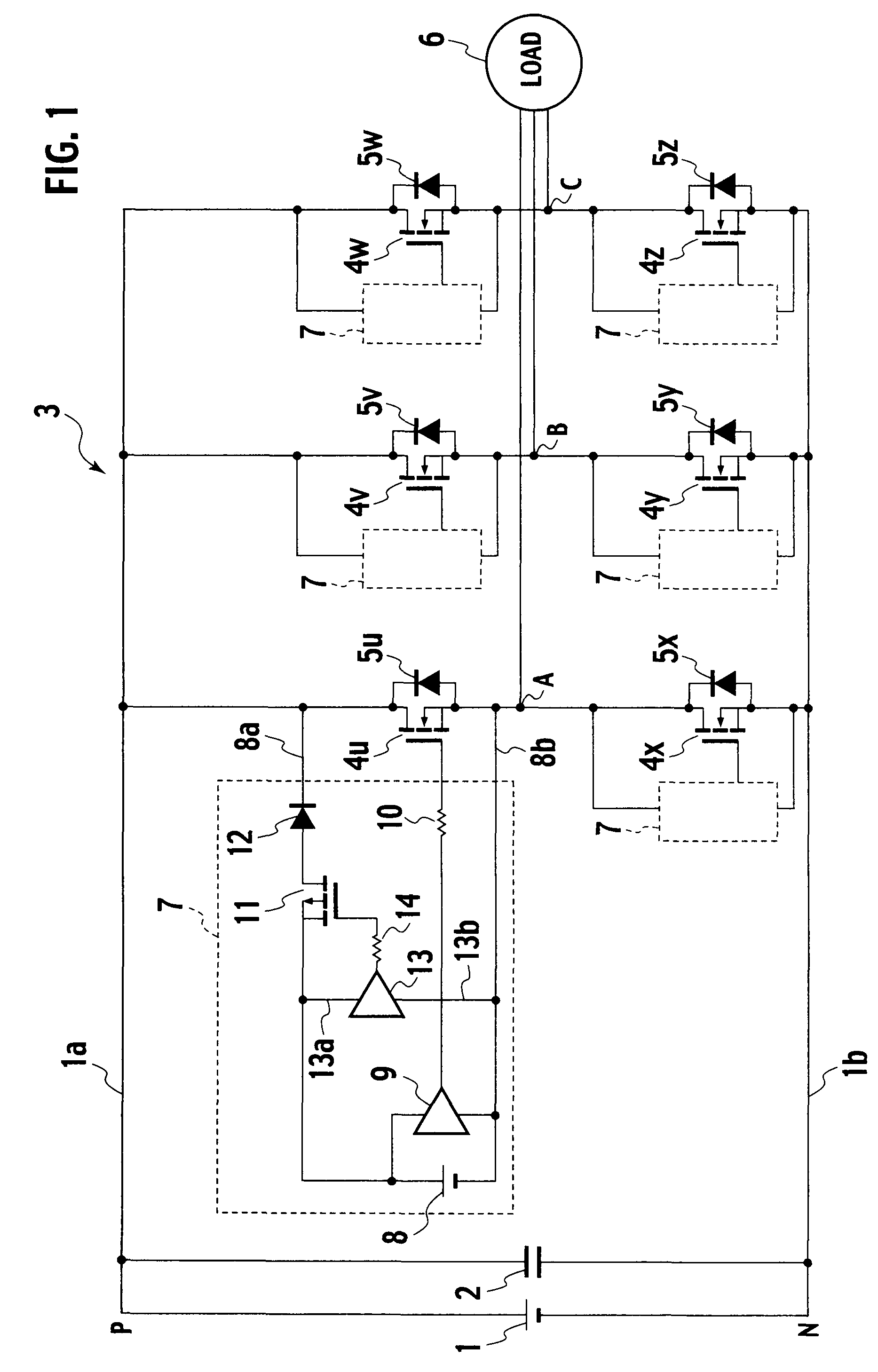
[0019]FIG. 1 is a circuit configuration diagram of an electric power conversion system according to the first embodiment of the present invention. In FIG. 1, a direct current voltage source 1 is implemented as a rectified three-phase alternating current power supply, for example; and as well as a smoothing capacitor 2, an inverter main circuit 3 is connected between a positive direct current bus 1a and a negative direct current bus 1b of the direct current voltage source 1. The inverter main circuit 3 is configured in the form of three-phase bridge connections of main circuit switching devices 4u, 4v, and 4w corresponding to main circuit switching devices of positive arms and main circuit switching devices 4x, 4y, and 4z of negative arms. Those main circuit switching devices 4u, 4v, 4w, 4x, 4y, and 4z have free wheeling diodes 5u, 5v, 5w, 5x, 5y, and 5z reverse parallel connected between positive electrodes and negative electrodes thereof, respectively. Further, the inverter main ci...

second embodiment

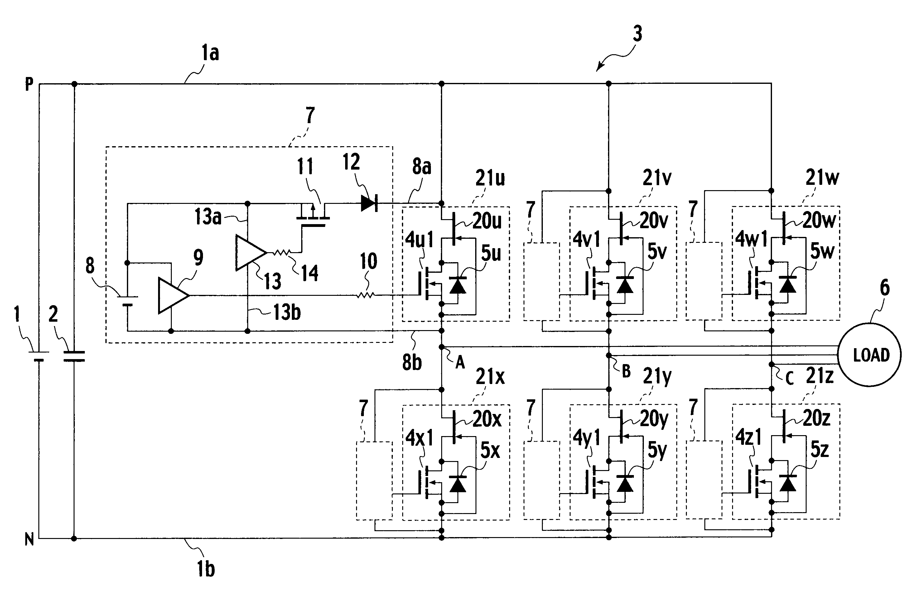
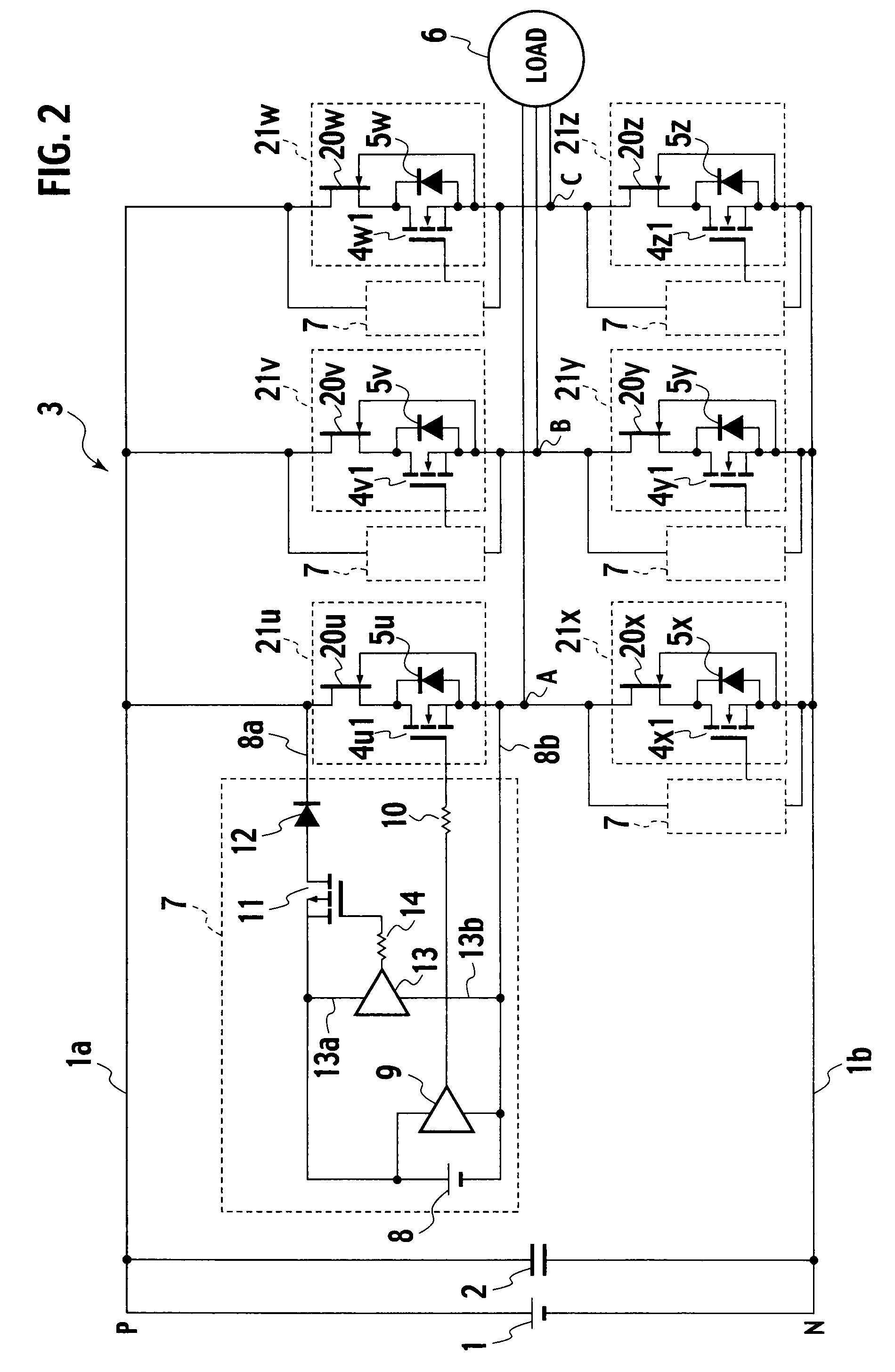
[0029]FIG. 2 is a circuit configuration diagram of an electric power conversion system according to the second embodiment of the present invention. As of parts of this embodiment, like parts to parts of the circuit configuration diagram of the electric power conversion system according to the first embodiment shown in FIG. 1 are designated by like reference characters, and description thereof is omitted. The present embodiment is different from the first embodiment in that it is configured such that main circuit switching devices 4u1, 4v1, 4w1, 4x1, 4y1, and 4z1 are low withstand-voltage devices, and those devices have at positive electrode ends thereof normally on switching devices 20u, 20v, 20w, 20x, 20y, and 20z inserted in series to those devices, respectively, the normally on switching devices 20u, 20v, 20w, 20x, 20y, and 20z having gates thereof connected to negative electrodes of the main circuit switching devices 4u, 4v, 4w, 4x, 4y, and 4z, respectively.

[0030]In a main circu...

third embodiment

[0038]FIG. 3 is a circuit configuration diagram of an electric power conversion system according to the third embodiment of the present invention. As of parts of this embodiment, like parts to parts of the circuit configuration diagram of the electric power conversion system according to the second embodiment shown in FIG. 2 are designated by like reference characters, and description thereof is omitted. The present embodiment is different from the second embodiment in that a current limiting resistor 15 is inserted at a positive electrode end of a low-voltage direct current power supply 8 of a reverse voltage application circuit 7A, and a high-frequency capacitor 16 is provided between the current limiting resistor 15 and a negative electrode of the low-voltage direct current power supply 8.

[0039]The low-voltage direct current power supply 8 has a voltage selected to one fourth of a voltage of a direct current voltage source 1, and the high-frequency capacitor 16 should not be any ...


PUM


Abstract

An electric power conversion system includes a DC power supply, plural main circuit switching devices bridge-connected to carry out DC / AC convert, having freewheeling diodes connected in reverse parallel thereto, respectively, and a reverse voltage application circuit for applying a reverse voltage smaller than the DC power supply to each freewheeling diode, upon a cutoff of back-flow current of the freewheeling diode, the reverse voltage application circuit being composed of a series connection of a low-voltage DC power supply, a reverse voltage application switching device having a lower withstand voltage than the main circuit switching devices and adapted to turn on upon a reverse recovery of the freewheeling diode, and an auxiliary diode having a shorter reverse recovery time than the freewheeling diode, the reverse voltage application switch being a device having holes as a majority carrier.

Description

TECHNICAL FIELD[0001]The present invention relates to an electric power conversion system, and in particular, to an electric power conversion system adapted for reduction of a loss at a free wheeling diode.BACKGROUND ART[0002]A typical inverter converts direct current from a direct current supply to alternating current by an inverter circuit with bridge-connected switching devices, to have alternating current outputs. For this, the load does not always have a power factor of 1, and a free wheeling diode is connected in reverse parallel to a respective switching device. In this configuration, as the switching device turns off, stored energy in the load flows back through the free wheeling diode.[0003]For a free wheeling diode conducting a forward current, if a switching device turns on in an arm with an opposite polarity to the free wheeling diode, a direct current voltage is applied as a reverse bias across the free wheeling diode. The free wheeling diode cuts off after a reverse cu...

Claims


Application Information

Patent Timeline
Patent Type & Authority Patents(United States)
IPC IPC(8): H02M3/24H02M7/5387
CPCH02M1/096H02M1/34H02M7/5387H02M7/5388Y02B70/1491H02M2001/0051H02M2001/342Y02B70/10H02M1/0051H02M1/342H02M7/515
Inventor KUZUMAKI, ATSUHIKOMOCHIKAWA, HIROSHIKOYAMA, TATEO
Owner KK TOSHIBA
Why Eureka
Try Eureka