
Determination of downhole pressure while pumping

a technology of downhole pressure and pumping, which is applied in the field of measuring downhole pressure, can solve the problems of inability to enable real-time decision, technique impractical for many wells, and rarely performed real-time measurements of bottom hole pressure with current technology, and achieve the effect of facilitating the calculation of depth

Active Publication Date: 2011-01-25
SCHLUMBERGER TECH CORP
View PDF44 Cites 9 Cited by
  • Summary
  • Abstract
  • Description
  • Claims
  • Application Information

AI Technical Summary

Benefits of technology

The patent describes an apparatus and method for calculating the depth at which a condition occurs in a borehole containing a fluid. This is achieved by generating a tubewave using a hollow body and a feature that initiates its generation based on exposure to physical properties such as pressure, time, temperature, pH, and background radiation. The tubewave can then be detected at a known depth and analyzed to calculate the depth of the condition. The technical effect of this invention is to provide a reliable and accurate means for determining the depth of a condition in a borehole, which can aid in the evaluation and management of oil and gas wells.

Problems solved by technology

However, real-time measurements of bottom hole pressure are rarely performed with current technology because the abrasiveness of a fracturing slurry is destructive to any exposed cable placed in the wellbore for delivering data to the surface.
Downhole memory gauges are sometimes used for selected treatments, but these do not enable real-time decision making during the treatment because their data is not delivered to the surface until after the treatment is over.
Although this technique has been used successfully on some wells, it is limited by the borehole depth and the types of rock layers through which a signal could be transmitted clearly.
These limitations render the technique impractical for use in many wells, and particularly in deep wells.
Indeed, tubewaves propagate with so little attenuation that they are the major source of noise in conventional borehole seismic surveys.

Method used


Image

  • Determination of downhole pressure while pumping
  • Determination of downhole pressure while pumping
  • Determination of downhole pressure while pumping

Examples


Embodiment Construction

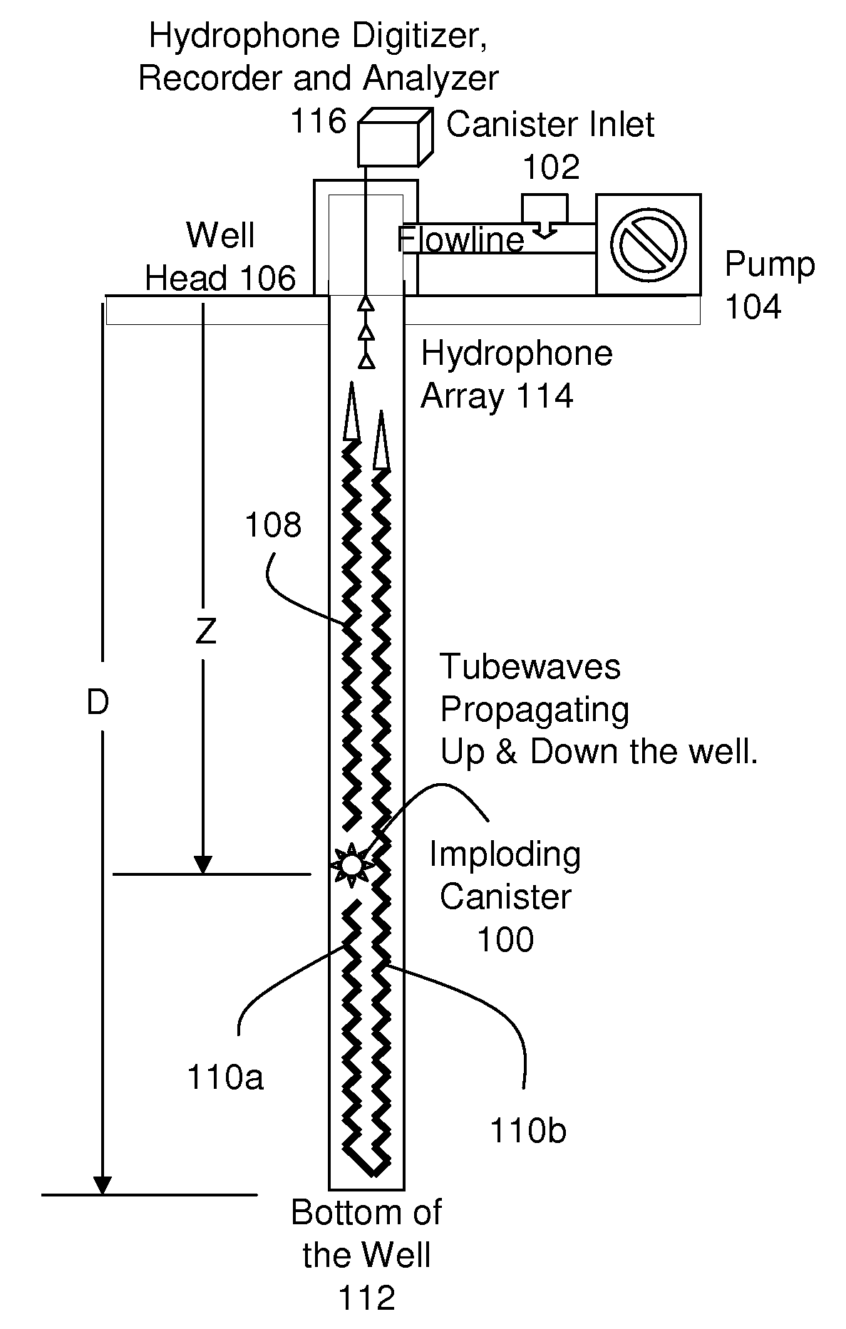
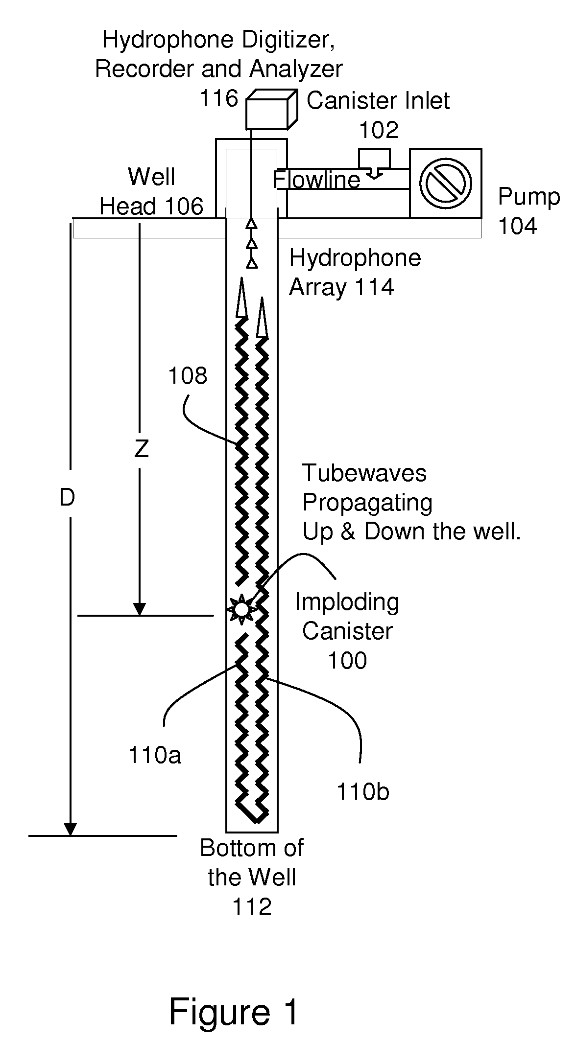
[0015]FIG. 1 illustrates use of an imploding canister (100) in a borehole to determine a pressure-depth relationship along the length of the borehole. The canister is introduced into the fluid being pumped into the borehole via an inlet (102) between the pump (104) and the borehole head (106). The canister (100) is designed to implode when the pressure to which it is subjected exceeds a predetermined implosion value, e.g., 300 PSI. Once introduced into the fluid, the canister is carried down the borehole by at least one of (a) the fluid being pumped and (b) the force of gravity. When the pressure to which the canister is subjected exceeds the implosion value, e.g., 300 PSI, the canister implodes. The implosion of the canister generates strong tubewaves (108, 110) which travel both up and down the well, i.e., an up-going tubewave (108) and a down-going tube wave (110a). The up-going tubewave (108) propagates upward through the borehole to the borehole head (106) at the surface. The d...


PUM


Abstract

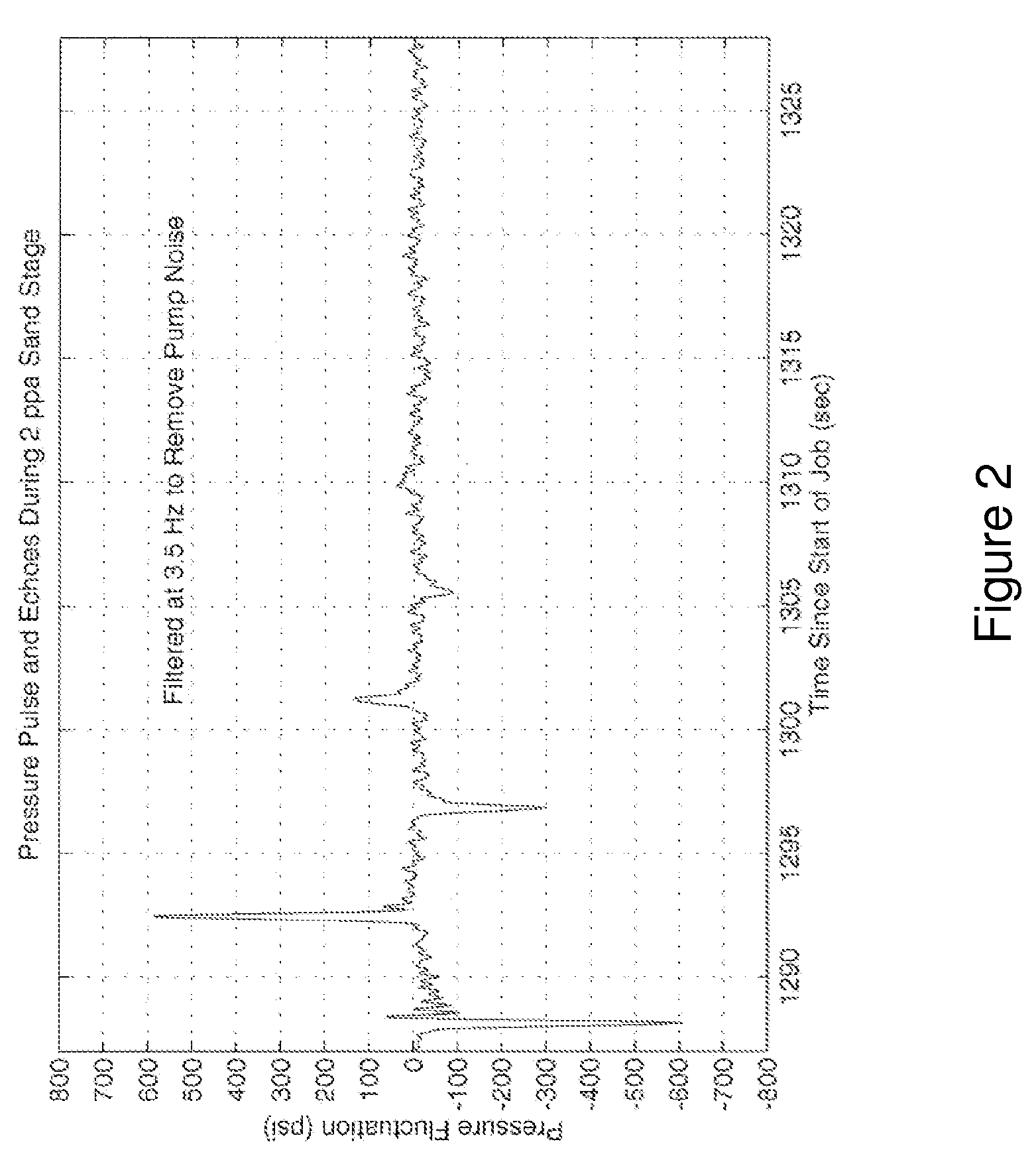
Tubewaves are used to transmit an indication of the depth at which a condition is detected in a well. In particular, the depth is calculated based on the difference in arrival time at the surface of a first tubewave which propagates directly upward in the borehole and a second tubewave which initially travels downward and is then reflected upward. The tubewaves may be generated by a canister designed to implode at a certain pressure. The canister is carried downhole by gravity and the fluid being pumped. At a depth at which its pressure tolerance is exceeded, it implodes and generates the tubewaves. An analyzer at the surface detects the tubewaves and generates a pressure versus depth profile of the well. Canisters may be acoustically tagged in order to generate tubewaves having particular frequency and amplitude characteristics. Canisters may also be configured to produce multiple implosions.

Description

FIELD OF THE INVENTION[0001]This invention is generally related to oil and gas wells, and more particularly to measurement of downhole pressure in a borehole during pumping operations.CROSS-REFERENCE TO RELATED APPLICATIONS[0002]This patent application is also related to the following commonly-assigned U.S. Patent Application which is hereby incorporated by reference in its entirety: application Ser. No. 11 / 691,071, entitled “Wireless Logging of Fluid Filled Boreholes”, filed on this same date.BACKGROUND OF THE INVENTION[0003]Achieving accurate, real-time bottom hole pressure measurements during borehole stimulation treatments has long been a goal in the oil and gas industry. During fracture treatments, in particular, accurate measurement of bottom hole pressure would allow an operator to observe fracture growth trends in real-time, and change treatment conditions accordingly. However, real-time measurements of bottom hole pressure are rarely performed with current technology becaus...

Claims


Application Information

Patent Timeline
Patent Type & Authority Patents(United States)
IPC IPC(8): E21B47/09E21B47/04
CPCE21B47/04E21B47/18E21B47/06
Inventor COATES, RICHARD TIMOTHYMILLER, DOUGLAS E.SULLIVAN, PHILIPAUZERAIS, FRANCOISHABASHY, TAREK M.
Owner SCHLUMBERGER TECH CORP
Learn More