Digital driver apparatus, method and system for solid state lighting

a technology of solid-state lighting and driver apparatus, applied in lighting and heating apparatus, process and machine control, instruments, etc., can solve problems such as system needs, led current fluctuation, and implementation of cpm, and achieve low-voltage ic implementations and cost reduction effects

Active Publication Date: 2011-02-01
CHEMTRON RES
View PDF3 Cites 196 Cited by
  • Summary
  • Abstract
  • Description
  • Claims
  • Application Information

AI Technical Summary

Benefits of technology

[0010]The exemplary embodiments of the present invention provide numerous advantages for providing power to solid state lighting, such as light emitting diodes. The exemplary embodiments allow for energizing one or more LEDs, using digital control and low side sensing, enabling low voltage IC implementations. The exemplary apparatus and system embodiments may be implemented with either fixed or variable frequency switching, and may be implemented with either AC or DC power sources. As a digital implementation, the exemplary embodiments may also be implemented at a reduced cost. The exemplary embodiments also provide for precise current control, within any selected tolerance levels. In addition, the exemplary embodiments also eliminate the required RC filtering of the prior art.
[0011]Further advantages of the exemplary embodiments further provide for controlling the intensity of light emissions for solid state devices such as LEDs, while simultaneously providing for substantial stability of perceived color emission, over both a range of intensities and also over a range of LED junction temperatures. The exemplary embodiments provide digital control, without requiring external compensation. The exemplary embodiments do not utilize significant resistive impedances in the current path to the LEDs, resulting in appreciably lower power losses and increased efficiency. The exemplary current regulator embodiments also utilize comparatively fewer components, providing reduced cost and size, while simultaneously increasing efficiency and enabling longer battery life when used in portable devices, for example.

Problems solved by technology

A CPM implementation, however, cannot simply utilize a controller for a Buck converter, but must also be accompanied with a circuit implementing DCM.
One challenge facing this CCM implementation is that the control system needs to transition between DCM and CCM modes in both directions.
Many prior art control systems will oscillate around these two modes, which causes LED current to fluctuate, and which may be visually apparent as flicker, for example.
When the outer compensator bandwidth may be low, another problem with this CCM technique is that the LED current may also fluctuate, particularly when the input voltage to the Buck converter contains a high ripple percentage.
This is typically not the case for an LED driver, however, which involves input voltages which are much higher than what a controller IC is capable of tolerating or specified to tolerate and, accordingly, such a high side sensing technique cannot be utilized with typical controller ICs.
Detailed analysis of this constant off time method shows that while it may be suitable for controlling Buck converter output voltage, it exhibits a very large error if it is used for controlling output current, due to converter component and environmental variations (e.g., manufacturing variations, component aging or life span, and environmental conditions such as temperature).

Method used


Image

  • Digital driver apparatus, method and system for solid state lighting
  • Digital driver apparatus, method and system for solid state lighting
  • Digital driver apparatus, method and system for solid state lighting

Examples


Embodiment Construction

[0042]While the present invention is susceptible of embodiment in many different forms, there are shown in the drawings and will be described herein in detail specific exemplary embodiments thereof, with the understanding that the present disclosure is to be considered as an exemplification of the principles of the invention and is not intended to limit the invention to the specific embodiments illustrated. In this respect, before explaining at least one embodiment consistent with the present invention in detail, it is to be understood that the invention is not limited in its application to the details of construction and to the arrangements of components set forth above and below, illustrated in the drawings, or as described in the examples. Methods and apparatuses consistent with the present invention are capable of other embodiments and of being practiced and carried out in various ways. Also, it is to be understood that the phraseology and terminology employed herein, as well as...


PUM


Abstract

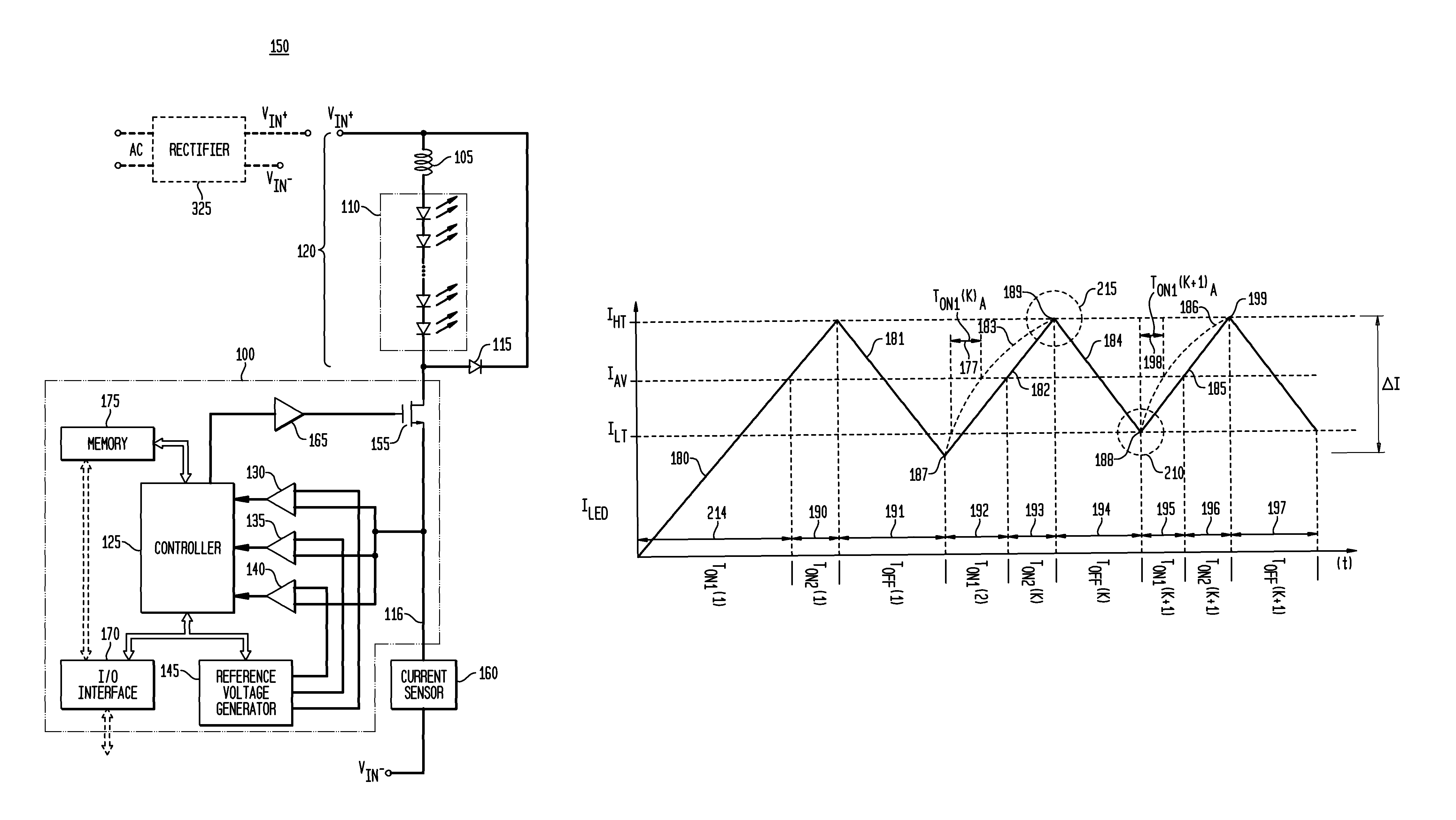
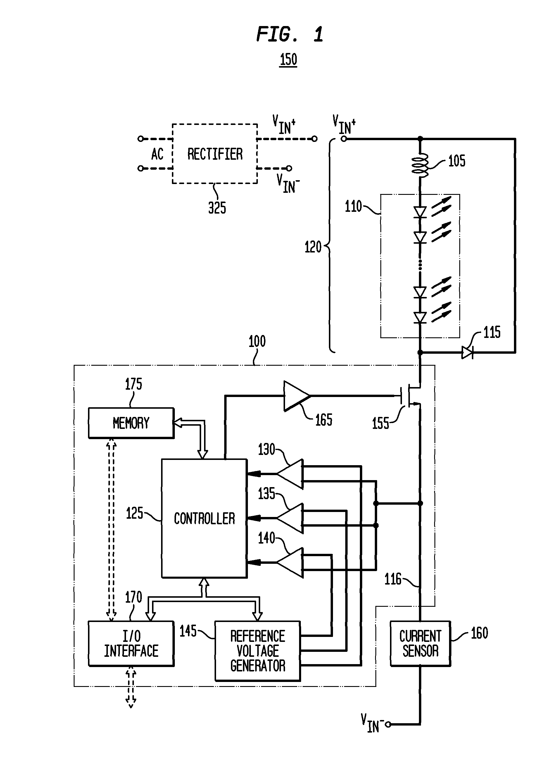
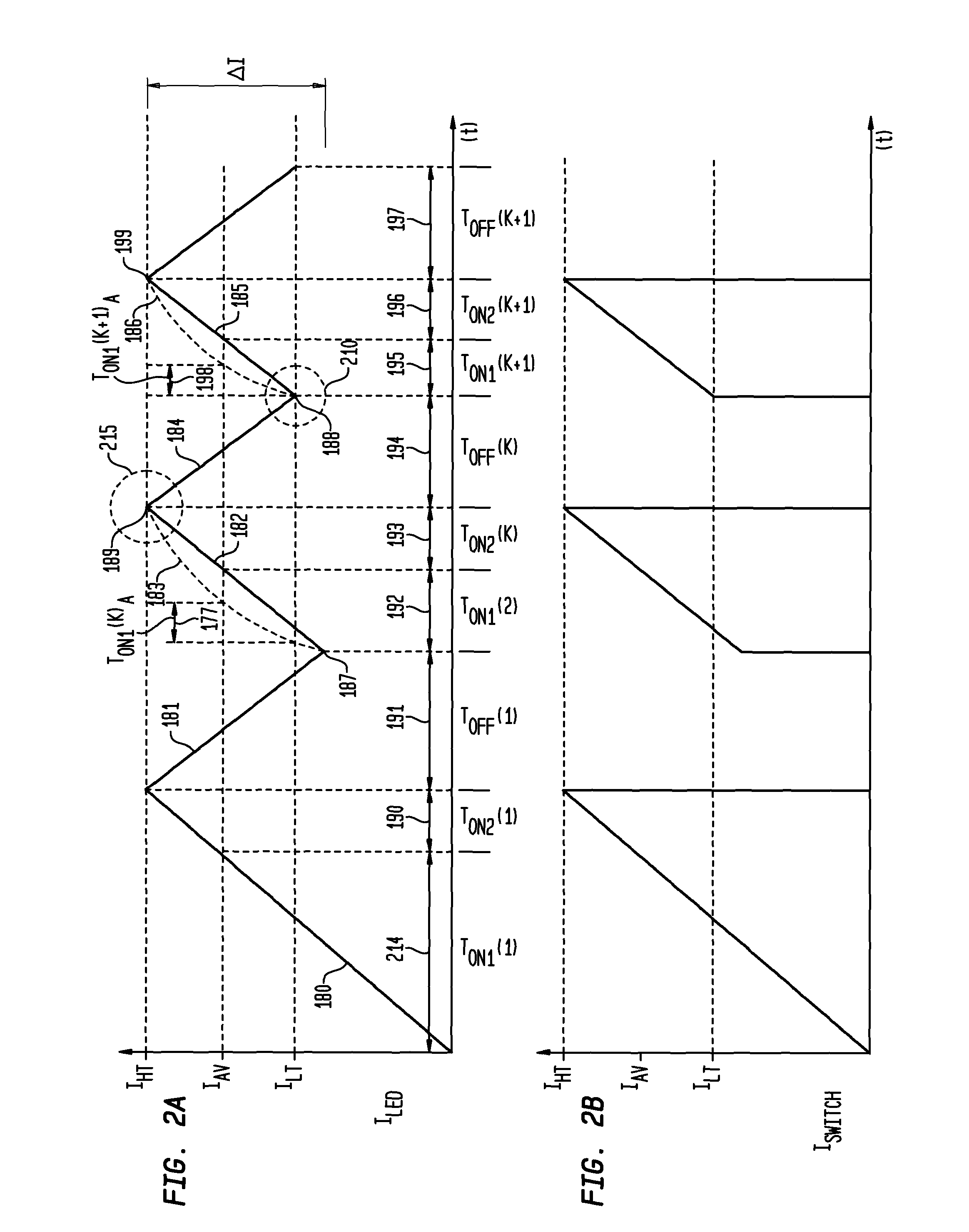
An apparatus, method and system are provided for controlling the solid state lighting, such as LEDs. An exemplary apparatus comprises: a switch for switching electrical current through the LEDs, a current sensor; a first comparator adapted to determine when a switch electrical current has reached a first predetermined threshold; a second comparator adapted to determine when the switch electrical current has reached a predetermined average current level; and a controller. The controller is adapted to turn the switch into an on state and an off state, to determine a first on time period as a duration between either a detection of a second predetermined current threshold or the turning the switch into the on state, and the detection of the predetermined average current level; to determine a second on time period as a duration between the detection of the predetermined average current level and the detection of the first predetermined current threshold; and to determine an on time period of the switch as substantially proportional to a sum of the first on time period and the second on time period. Additional exemplary embodiments utilize a difference between the first and second on time periods to generate an error signal to adjust the on time period of the switch.

Description

FIELD OF THE INVENTION[0001]The present invention in general is related to supplying and controlling power to solid state lighting devices, and more particularly, to digitally controlling the current of solid state lighting devices such as light emitting diodes utilized in lighting and other applications.BACKGROUND OF THE INVENTION[0002]Arrays of light emitting diodes (“LEDs”) are utilized for a wide variety of applications, including for general lighting and multicolored lighting. Because emitted light intensity is proportional to the average current through an LED (or through a plurality of LEDs connected in series), adjusting the average current through the LED(s) is one typical method of regulating the intensity or the color of the illumination source. Solid state lighting, such as LEDs, are typically coupled to a converter as a power source.[0003]A step-down (Buck) converter can be controlled either in discontinuous conduction mode (DCM) or continuous conduction mode (CCM). Typ...

Claims


Application Information

Patent Timeline
Patent Type & Authority Patents(United States)
IPC IPC(8): H05B41/16G09G3/36
CPCH05B33/0818H05B45/3725H05B45/375
Inventor ZHOU, DONGSHENGSHTEYNBERG, ANATOLYRODRIGUEZ, HARRYEASON, MARKNGUYEN, LANH
Owner CHEMTRON RES
Why Eureka
Try Eureka