
Cell assembly for an energy storage device with activated carbon electrodes

a technology of activated carbon electrodes and cell assemblies, which is applied in the direction of cell components, final product manufacturing, sustainable manufacturing/processing, etc., can solve the problems of corrosion of current collectors, carbon electrode current collection methods that are significantly different from those of lead electrodes, and carbon electrode contact resistance, etc., to achieve the effect of convenient assembly

Active Publication Date: 2011-02-01
WAINWRIGHT D WALKER
View PDF70 Cites 16 Cited by
  • Summary
  • Abstract
  • Description
  • Claims
  • Application Information

AI Technical Summary

Benefits of technology

"The present invention provides an energy storage device with a flexible and economical method of creating a multi-plate hybrid battery / supercapacitor energy storage device. The device includes a cell assembly with a carbon electrode and a current collector assembly, which are both adhered to and in electrical contact with each other. The carbon electrode is made of a sheet of highly conductive material sandwiched between two sheets of electrically conductive shield material. The shield material is chemically resistant and electrochemically stable in the electrolyte during operation of the device. The cell assembly is easy to assemble into multi-plate cells and is manufacturable by conventional processes with economical materials. The technical effects of the invention include providing a flexible and economical method of creating a multi-plate hybrid battery / supercapacitor energy storage device, providing a chemically compatible highly conductive interface for the carbon electrode, and providing a manufacturable cell assembly for an energy storage device."

Problems solved by technology

One problem with the use of conventional lead-acid battery components within devices such as those disclosed herein is that the current collection methods needed for the carbon electrodes are significantly different than those of the lead electrodes.
Another problem is corrosion of the current collector.
A further problem is the contact resistance between the current collector and the carbon electrode.

Method used


Image

  • Cell assembly for an energy storage device with activated carbon electrodes
  • Cell assembly for an energy storage device with activated carbon electrodes
  • Cell assembly for an energy storage device with activated carbon electrodes

Examples


Embodiment Construction

[0039]The novel features which are believed to be characteristic of the present invention, as to its structure, organization, use and method of operation, together with further objectives and advantages thereof, will be better understood from the following discussion.

[0040]Turning now to the drawings, in which similar reference characters denote similar elements throughout the several views, the attached figures illustrate various embodiments of cell assemblies for a supercapacitor energy storage device in keeping with the present invention.

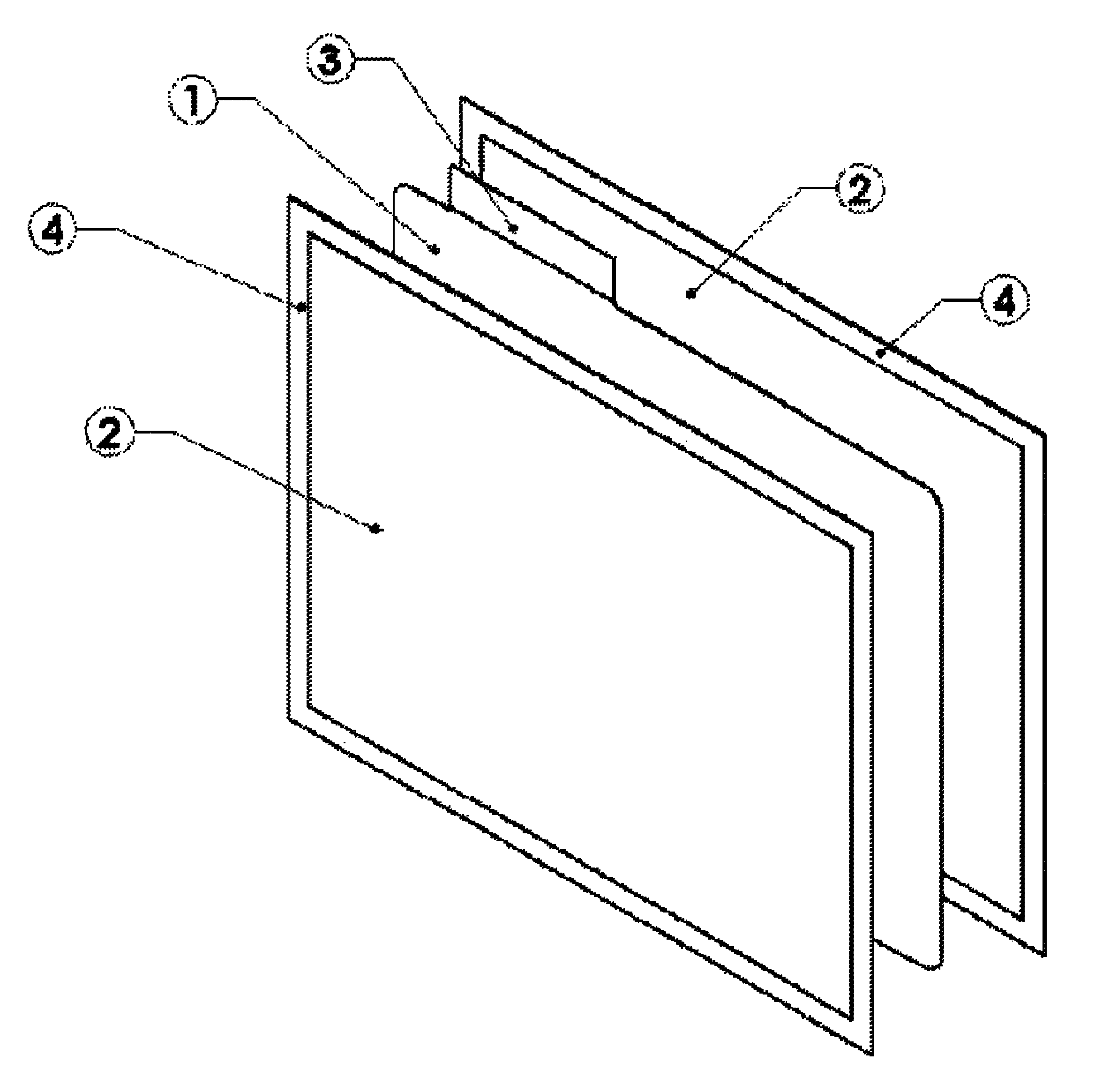
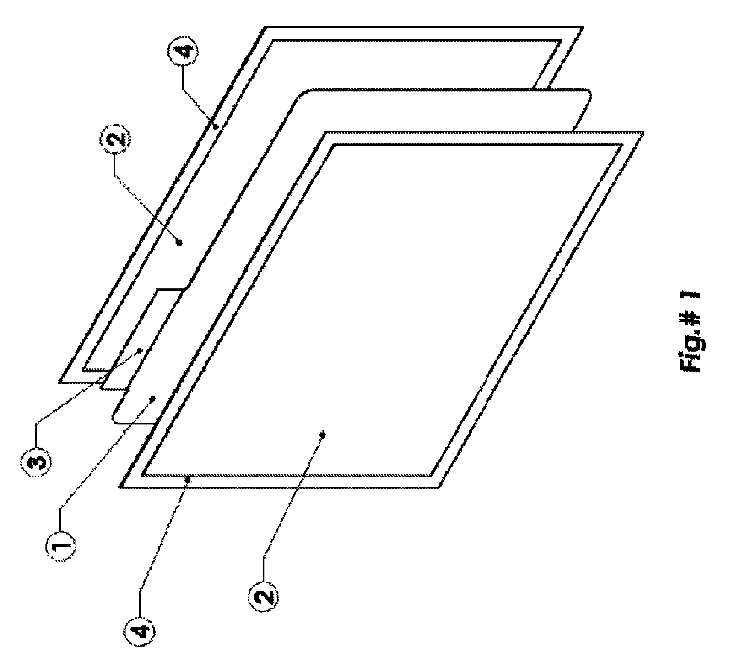
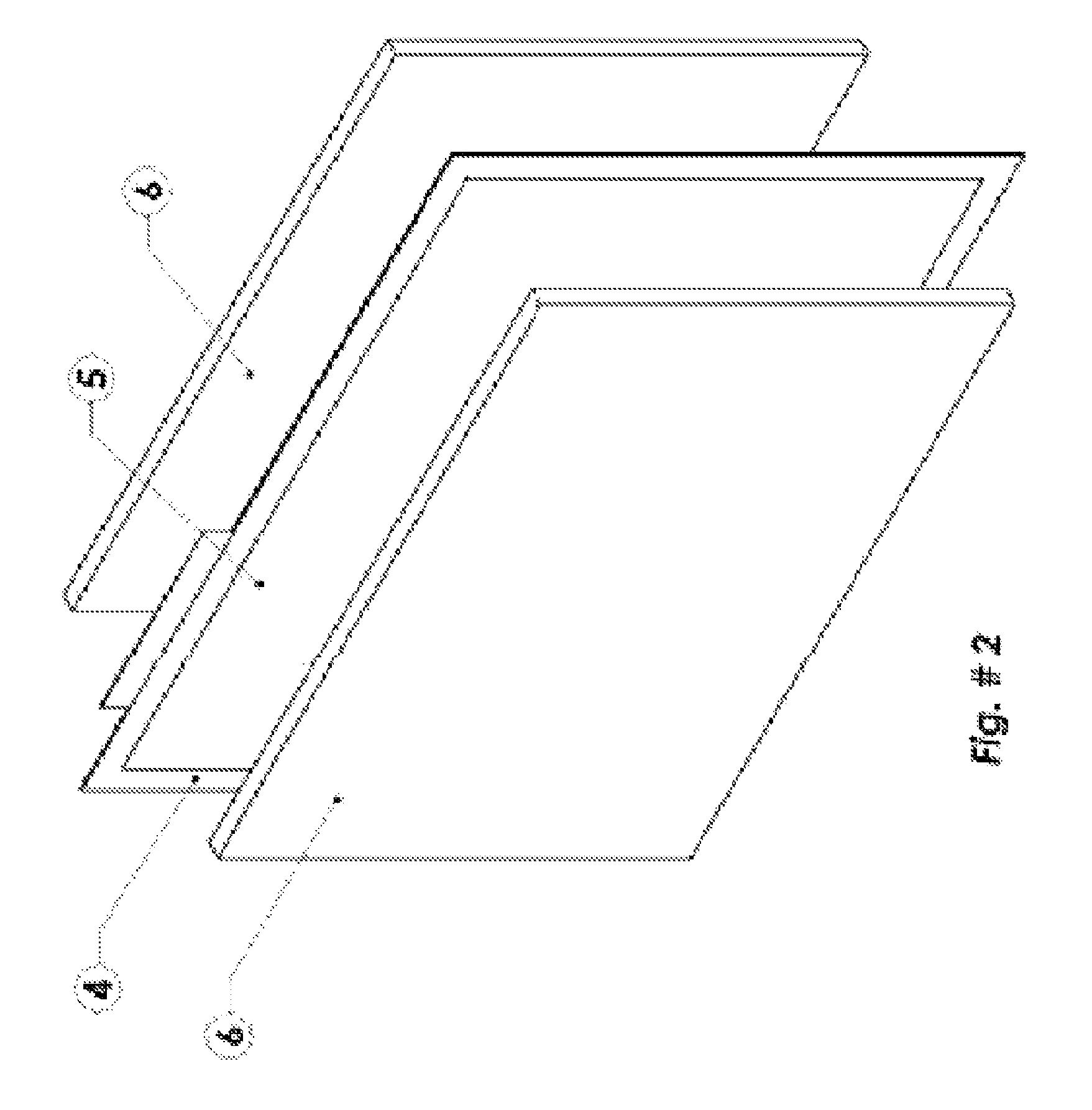
[0041]Referring now to FIG. 1, a current collector (1) is made from a thin sheet of material, commonly by a die cut process. The material is most commonly a highly conductive metal. In this embodiment, the collector shown is a thin, flat sheet of copper, but other highly conductive metals may include copper alloys, titanium, aluminum, silver, stainless steel, nickel, and mixtures and combinations thereof. The metal sheet may be manufactured in va...


PUM

PropertyMeasurementUnit
electronically conductiveaaaaaaaaaa
flexibleaaaaaaaaaa
energyaaaaaaaaaa

Abstract

A hybrid supercapacitor energy storage device includes at least one lead electrode, at least one carbon electrode, a separator, a casing, and an acid electrolyte. The lead electrode is enveloped in a common glass mat separator known in the lead-acid battery industry. The carbon electrode comprises a highly conductive current collector which is a sheet or other metal material sandwiched between two sheets of electronically conductive shield material. Activated carbon is manufactured using a binder such as polyethylene or PTFE adhered to and in electrical contact with the shield material of the current collector.

Description

I. FIELD OF THE INVENTION[0001]The present invention relates generally to an electric energy storage device, and more specifically it relates to a cell assembly for a flexible and economical multi-plate hybrid battery supercapacitor having lead-based electrodes and carbon-based electrodes.II. BACKGROUND OF THE INVENTION[0002]Typically, the most common electrical energy storage devices are electrochemical batteries and capacitors, including supercapacitors. The device disclosed herein is an implementation of a hybrid lead acid battery and activated carbon supercapacitor, having features and performance characteristics that are distinct from either a battery or a supercapacitor.[0003]The energy in this type of hybrid device is stored both electrostatically and electrochemically. The device in keeping with the present invention has a significantly greater cycle life and shorter charge time than a lead-acid battery. The present device also has a much higher energy density than a convent...

Claims


Application Information

Patent Timeline
Patent Type & Authority Patents(United States)
IPC IPC(8): H01G9/00H01M6/04H01M4/56
CPCH01G9/016H01G9/058H01G9/155H01G11/04H01G11/12H01G11/38H01G11/80H01G11/58Y02E60/13H01G11/74H01G11/22Y02P70/50
Inventor BUIEL, EDWARD R.ESHKENAZI, VICTORRABINOVICH, LEONIDSUN, WEIVICHNYAKOV, VLADIMIRSWIECKI, ADAM J.COLE, JOSEPH E.
Owner WAINWRIGHT D WALKER
Learn More