Wound electric double-layer capacitor

a double-layer capacitor and electric double-layer technology, applied in the direction of electrolytic capacitors, liquid electrolytic capacitors, electrochemical generators, etc., can solve the problems of gas generation, resistance increase, capacity reduction, character degradation, etc., to reduce the characteristic degradation, suppress the electrochemical reaction, and high performance

Active Publication Date: 2011-02-01
PANASONIC CORP
View PDF16 Cites 62 Cited by
  • Summary
  • Abstract
  • Description
  • Claims
  • Application Information

AI Technical Summary

Benefits of technology

[0025]The present invention addresses the conventional problems, and provides a wound electric double-layer capacitor that suppresses electrochemical reaction on the surface of a polarized electrode layer, reduces the characteristic degradation, and has high performance.
[0030]Thus, in the wound electric double-layer capacitor of the present invention, the polarized electrode layers formed in the negative electrode are wound at least one extra turn from the winding end of the polarized electrode layers that are formed in the positive electrode of the capacitor element, and hence a part where the polarized electrode layers formed in the negative electrode face each other through the separator is formed on the outermost peripheral surface of the capacitor element. Therefore, the potential of the polarized electrode layers can be set in an electrochemically stable region where the electrolyte for driving or a member such as the current collector constituting each electrode does not cause electrochemical reaction. It is prevented that BF4−, PF6− or the like of electrolyte anion is concentrated to the surface of the positive electrode to make the surface acidic, so that the separator does not degrade. Therefore, gas generation, resistance increase, and capacity reduction caused by the electrochemical reaction are prevented, and a wound electric double-layer capacitor that hardly undergoes characteristic degradation and has high reliability can be achieved.
[0036]Thus, in the wound electric double-layer capacitor of the present invention, the part having no polarized electrode layer is disposed in one electrode of the wound capacitor element that faces, through the separator, the coupling part of the lead wire coupled to at least the other electrode. Therefore, between the coupling part of the lead wire coupled to the negative electrode and the part having no polarized electrode layer that is disposed in the facing positive electrode, it is prevented that BF4−, PF6− or the like of electrolyte anion is attracted to the positive electrode side due to the chemical reaction of the electrolyte for driving, and hence the separator can be prevented from degrading. Also between the coupling part of the lead wire coupled to the positive electrode and the part having no polarized electrode layer that is disposed in the facing negative electrode, the alkaline component is not attracted to the negative electrode side, so that the separator can be prevented from degrading.
[0039]Thus, in the wound electric double-layer capacitor of the present invention, the cathode foil of the capacitor element is made longer, and is wound at least beyond the winding end of the anode foil. Therefore, the potential of the electrode can be set in an electrochemically stable region where the electrolyte for driving or a member such as the anode foil or cathode foil does not cause electrochemical reaction. Since the cathode foil is disposed on the outermost surface of the capacitor element, it is prevented that BF4−, PF6− or the like of electrolyte anion is concentrated to the surface of the anode foil to make the surface acidic, and hence the separator does not degrade. As a result, gas generation, resistance increase, and capacity reduction caused by the electrochemical reaction are prevented, and a wound electric double-layer capacitor that hardly undergoes characteristic degradation and has high reliability can be achieved.

Problems solved by technology

This polarization causes electrochemical reaction on the surface of the polarized electrode layer of each electrode to cause characteristic degradation such as gas generation, resistance increase, and capacity reduction, disadvantageously.

Method used


Image

  • Wound electric double-layer capacitor
  • Wound electric double-layer capacitor
  • Wound electric double-layer capacitor

Examples


first exemplary embodiment

[0064]The first exemplary embodiment will be described hereinafter.

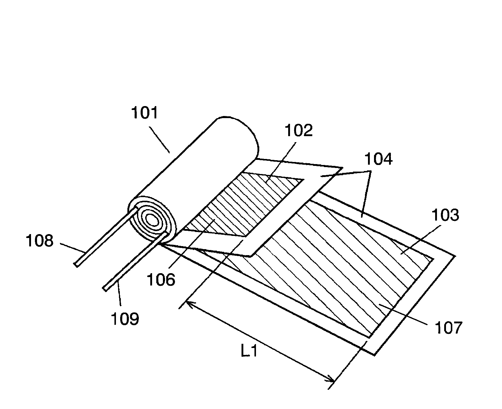
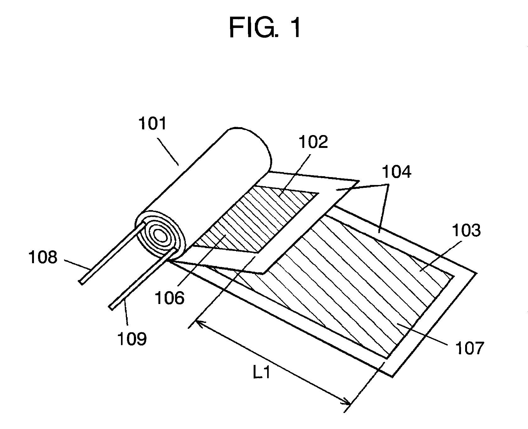
[0065]FIG. 1 is a developed perspective view showing a structure of a capacitor element used in a wound electric double-layer capacitor in accordance with the first exemplary embodiment of the present invention. In FIG. 1, capacitor element 101 is formed by winding positive electrode 102 and negative electrode 103 while separator 104 is interposed between them.

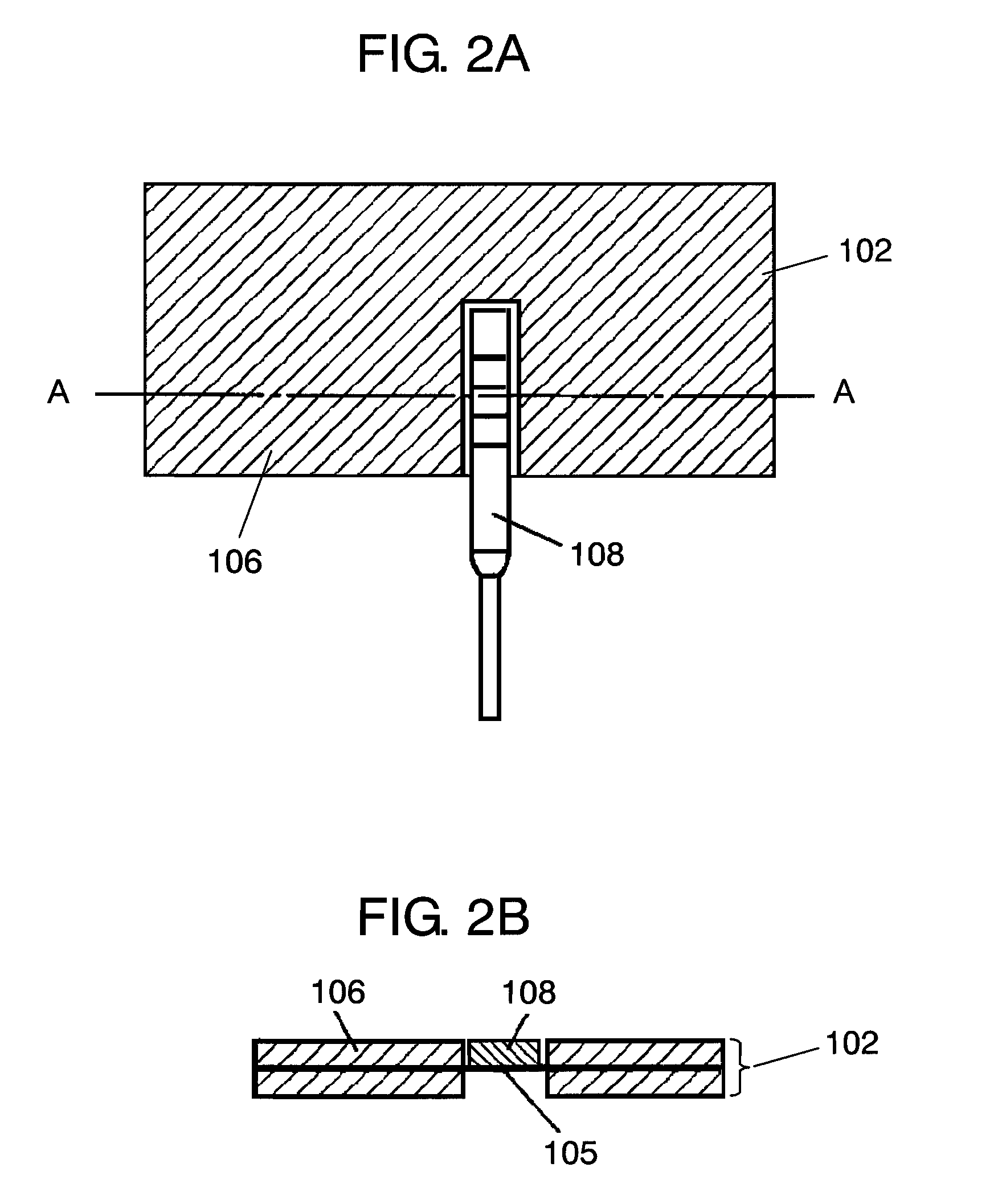
[0066]Positive electrode 102 is formed by disposing polarized electrode layers 106 on both surfaces of current collector 105 made of a metal foil described later, and negative electrode 103 is formed by disposing polarized electrode layers 107 on both surfaces of current collector 105. Positive electrode 102 is coupled to positive electrode lead wire 108, and negative electrode 103 is coupled to negative electrode lead wire 109. The coupling states of positive electrode lead wire 108 and negative electrode lead wire 109 are described below. As shown in detail i...

example 1

[0075]A high-purity aluminum foil (Al: 99.99% or more) with a thickness of 30 μm is used as the current collector made of a metal foil, and is electrolyte-etched in a hydrochloric-acid-based etchant to roughen the surface of the aluminum foil.

[0076]Next, polarized electrode layers are formed on both surfaces of this aluminum foil. For forming the polarized electrode layers, activated carbon powder of phenol resin base of an average grain size of 5 μm, carbon black of an average grain size of 0.05 μm as a conductive adding agent, and a water-soluble binder solution in which carboxymethyl cellulose (CMC) is dissolved are mixed at weight percentage of 10:2:1, and are sufficiently kneaded by a kneader. Dispersion solvent of methanol and water is gradually added to the kneaded product, and the resultant product is further kneaded to produce paste of a predetermined viscosity. Then, this paste is applied to the surface of the aluminum foil, and dried in the atmosphere at 100° C. for one h...

example 2

[0082]A wound electric double-layer capacitor is produced similarly to example 1 except that the positive electrode and negative electrode are disposed as shown in FIG. 3, width W1 of the positive electrode is set at 40 mm, and width W2 of the negative electrode is set at 44 mm.


PUM


Abstract

A wound electric double-layer capacitor suppresses electrochemical reaction on polarized electrode layers, reduces characteristic degradation, and has high reliability. The capacitor has a capacitor element formed by winding positive and negative electrodes with a separator interposed between them, a metal case for storing the capacitor element and an electrolyte for driving, and a sealing member for sealing an opening of the metal case. In the positive and negative electrodes, positive and negative electrode lead wires are coupled to exposed parts of current collectors having polarized electrode layers on their both surfaces, respectively. The negative electrode is wound at least one extra turn from the winding end of the positive electrode of the capacitor element, and hence a part where the polarized electrode layers formed in the negative electrode face each other through the separator is formed on the outermost periphery of the capacitor element.

Description

TECHNICAL FIELD[0001]The present invention relates to a wound electric double-layer capacitor used in various electronic devices.BACKGROUND ART[0002]FIG. 10A is an exploded perspective view showing a structure of a conventional wound electric double-layer capacitor used in various electronic devices. FIG. 10B is a developed perspective view showing a structure of a capacitor element used in the capacitor. In FIG. 10A and FIG. 10B, capacitor element 431 is formed by winding positive electrode 434 and negative electrode 435 in a state where separator 436 is interposed between them.[0003]Each of positive electrode 434 and negative electrode 435 is formed by disposing polarized electrode layers (not shown) on both surfaces of a current collector (not shown) made of a metal foil, and positive electrode lead wire 432 is coupled to positive electrode 434, and negative electrode lead wire 433 is coupled to negative electrode 435.[0004]Capacitor element 431 having such a structure is impregn...

Claims


Application Information

Patent Timeline
Patent Type & Authority Patents(United States)
IPC IPC(8): H01G9/00H01G11/74H01G11/82
CPCH01G9/016H01G9/058H01G9/155H01G11/74H01G11/82Y02E60/13H01G11/28H01G11/14H01G11/78H01G11/26H01G11/52H01G11/22
Inventor HIROSE, ERITAKAMUKU, YOSHINORIITO, YASUYUKIONISHI, SATOMI
Owner PANASONIC CORP
Why Eureka
Try Eureka