
System and method for nanotube growth via Ion implantation using a catalytic transmembrane

a technology of nanotubes and ion implantation, applied in the field of nanotubes, can solve the problems of generally poor quality mwnts or swnts of cvd, and achieve the effect of facilitating sustained growth of high quality nanotubes

Active Publication Date: 2011-02-08
RAYTHEON CO
View PDF2 Cites 8 Cited by
  • Summary
  • Abstract
  • Description
  • Claims
  • Application Information

AI Technical Summary

Benefits of technology

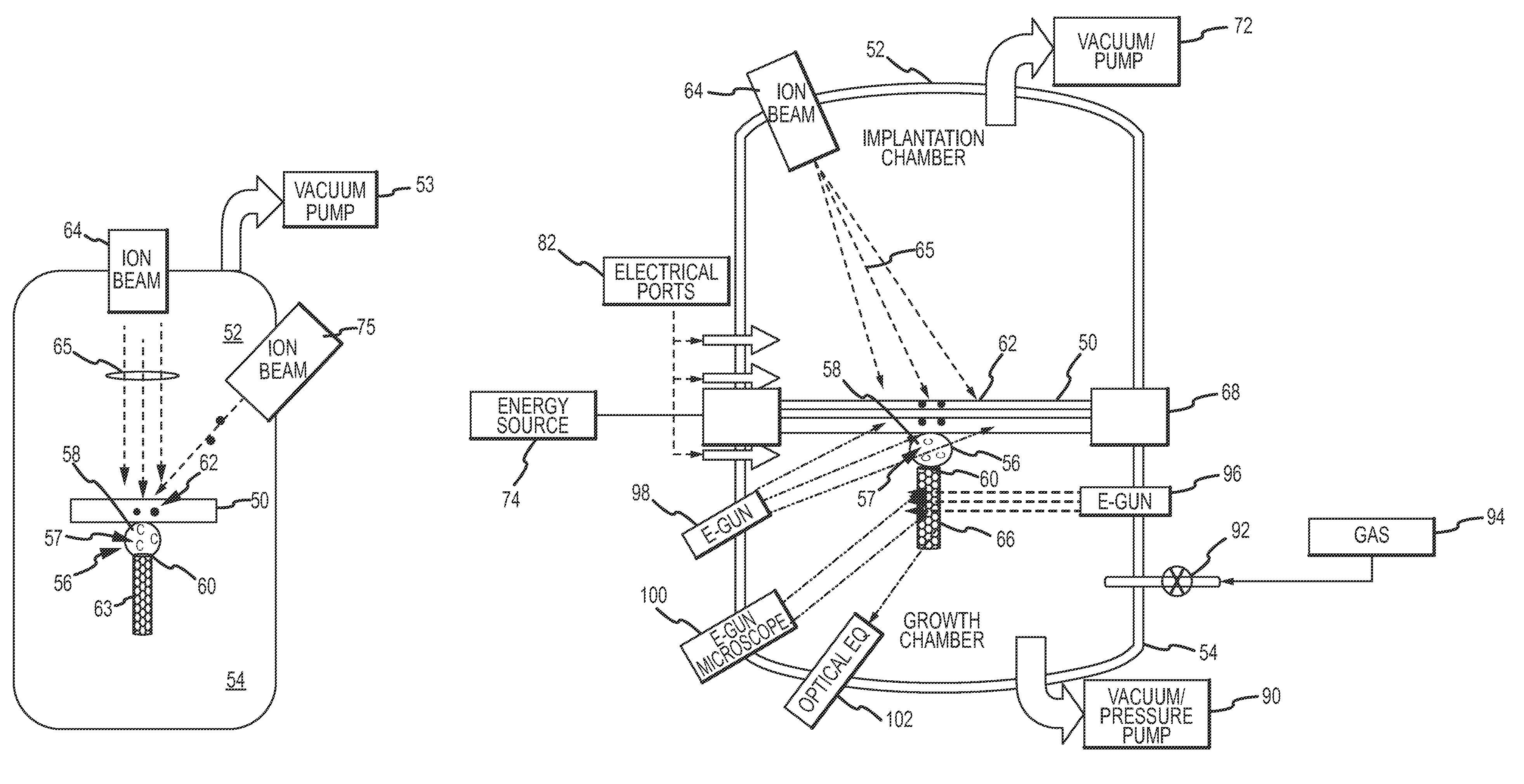
The present invention provides a system and method for growing nanotubes using an ion implantation process. This allows for the sustained growth of high quality nanotubes. By implanting ions into a catalyst and growing nanotubes on an opposing surface exposed to the growth chamber, the carbon ions can be directly or indirectly implanted into the catalyst. This process provides greater flexibility and control over the implantation and growth processes.

Problems solved by technology

CVD generally produces MWNTs or SWNTs of relatively poor quality due mostly to the poorly controlled diameters of the nanotubes.

Method used


Image

  • System and method for nanotube growth via Ion implantation using a catalytic transmembrane
  • System and method for nanotube growth via Ion implantation using a catalytic transmembrane
  • System and method for nanotube growth via Ion implantation using a catalytic transmembrane

Examples


Embodiment Construction

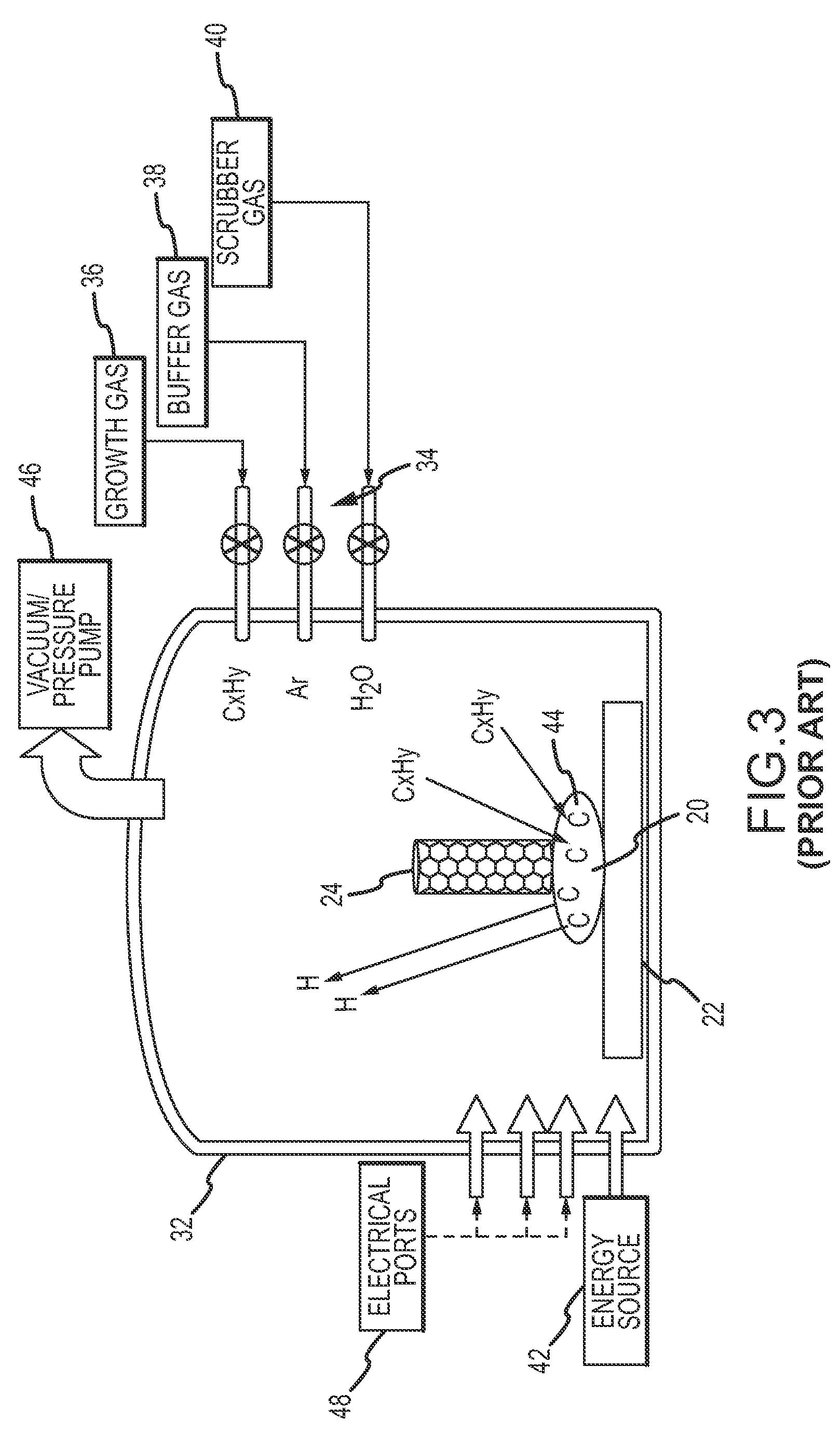
[0027]Efforts to improve the growth of CNTs have revealed a number of drawbacks in the conventional CVD approach. The surface area of the catalytic particle for absorbing carbon atoms is limited by the desired geometry and growth of the CNT from the catalytic nano-particle. That is, the growing CNT covers most of the catalyst. To grow a SWNT the nano-particle must be very small, approximately 1-10 nm in diameter. The presence of the growing CNT further reduces the available surface area. Furthermore, the absorption process itself causes the surface of the catalytic nano-particle to become encrusted with amorphous carbon and graphite which slows and eventually stops absorption of feedstock carbon and growth of the CNT. The effectiveness of the scrubber gas to clean the surface of the nano-particle is limited because the scrubber gas tends to attack the CNT necessitating a lower concentration of scrubber gas. The conventional process cannot be sustained indefinitely, which places a li...


PUM

PropertyMeasurementUnit
densitiesaaaaaaaaaa
elastic modulusaaaaaaaaaa

Abstract

Ion implantation is used to grow nanotubes out of carbon and other materials. Catalytic material is placed on or in a membrane that physically and possibly environmentally separates an implantation chamber or region from a growth chamber or region. High-energy ions are implanted into the catalytic material from one side to grow nanotubes on an exposed surface in the growth chamber. Ion implantation via the membrane provides for greater flexibility to separate and independently control the implantation and growth processes.

Description

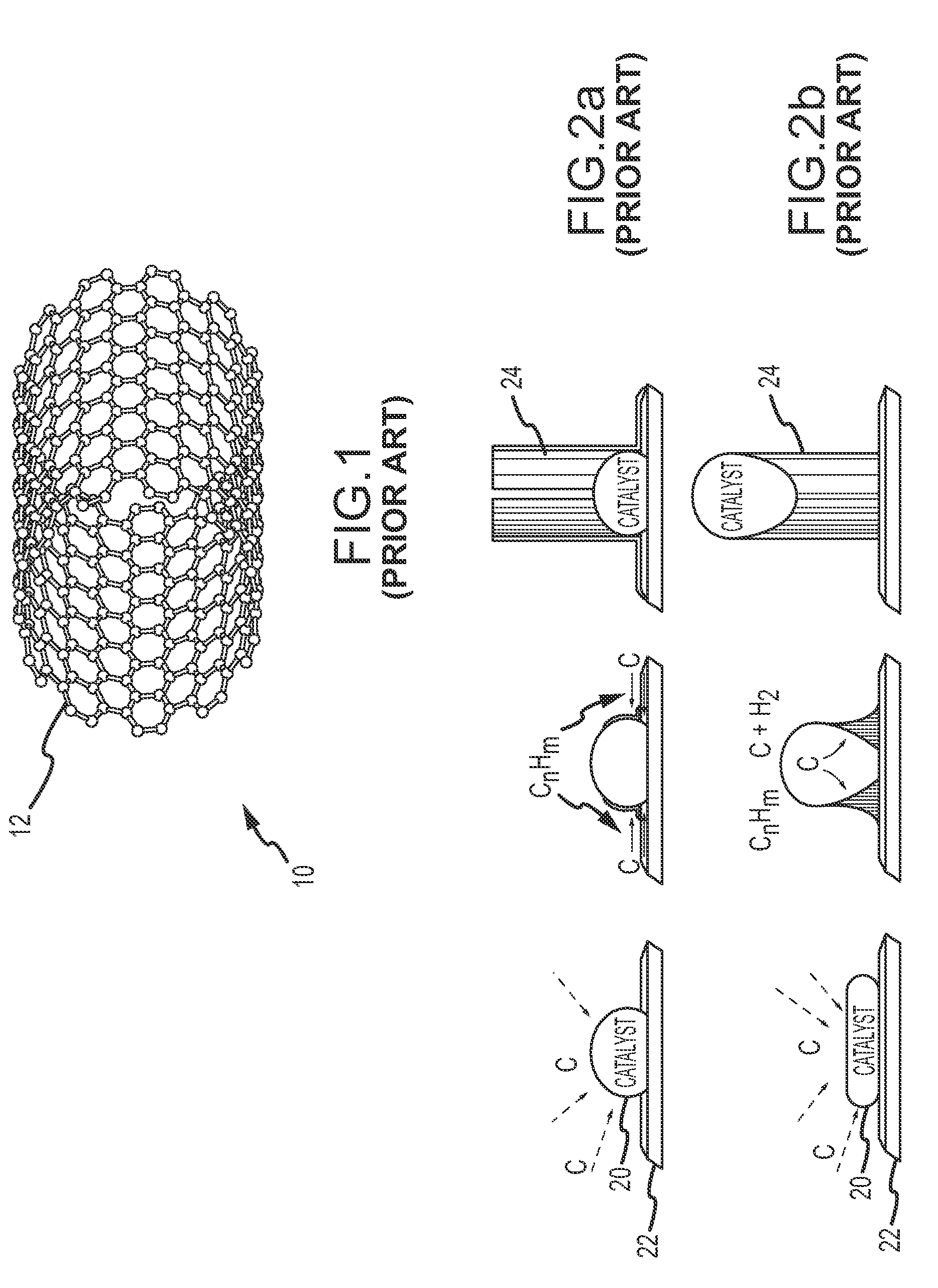
BACKGROUND OF THE INVENTION[0001]1. Field of the Invention[0002]This invention relates to nanotube (NT) growth of carbon and other materials using an ion implantation process.[0003]2. Description of Related Art[0004]Carbon nanotubes (CNTs) have stimulated a great deal of interest in the microelectronic and other industries because of their unique properties including tensile strengths above 35 GPa, elastic modulus reaching 1 TPa, higher thermal conductivity than diamond, ability to carry 1000× the current of copper, densities below 1.3 g / cm3 and high chemical, thermal and radiation stability. CNTs have great promise for devices such as field effect transistors, field emission displays, single electron transistors in the microelectronic industry, and uses in other industries. Commercialization of CNTs will depend in large part on the ability to grow and network CNTs on a large cost-effective scale without compromising these properties.[0005]As illustrated in FIG. 1, a CNT 10 is a hol...

Claims


Application Information

Patent Timeline
Patent Type & Authority Patents(United States)
IPC IPC(8): C23C16/00C23C16/448
CPCC01B21/064C01B31/02C01B31/36C01B33/02C01B35/02Y10S977/844C01B32/05
Inventor BARKER, DELMAR L.JORDAN, MEAD M.POISL, W. HOWARD
Owner RAYTHEON CO
Learn More