

Image noise reduction device and image noise reduction method
a noise reduction device and noise reduction technology, applied in the field of processing image data, can solve the problems of failure to reproduce the shooting environment, auto adjustment of image quality by image processing application program, etc., and achieve the effect of favorable image processing results
- Summary
- Abstract
- Description
- Claims
- Application Information
AI Technical Summary
Benefits of technology
Problems solved by technology
Method used
Image

Examples
first embodiment
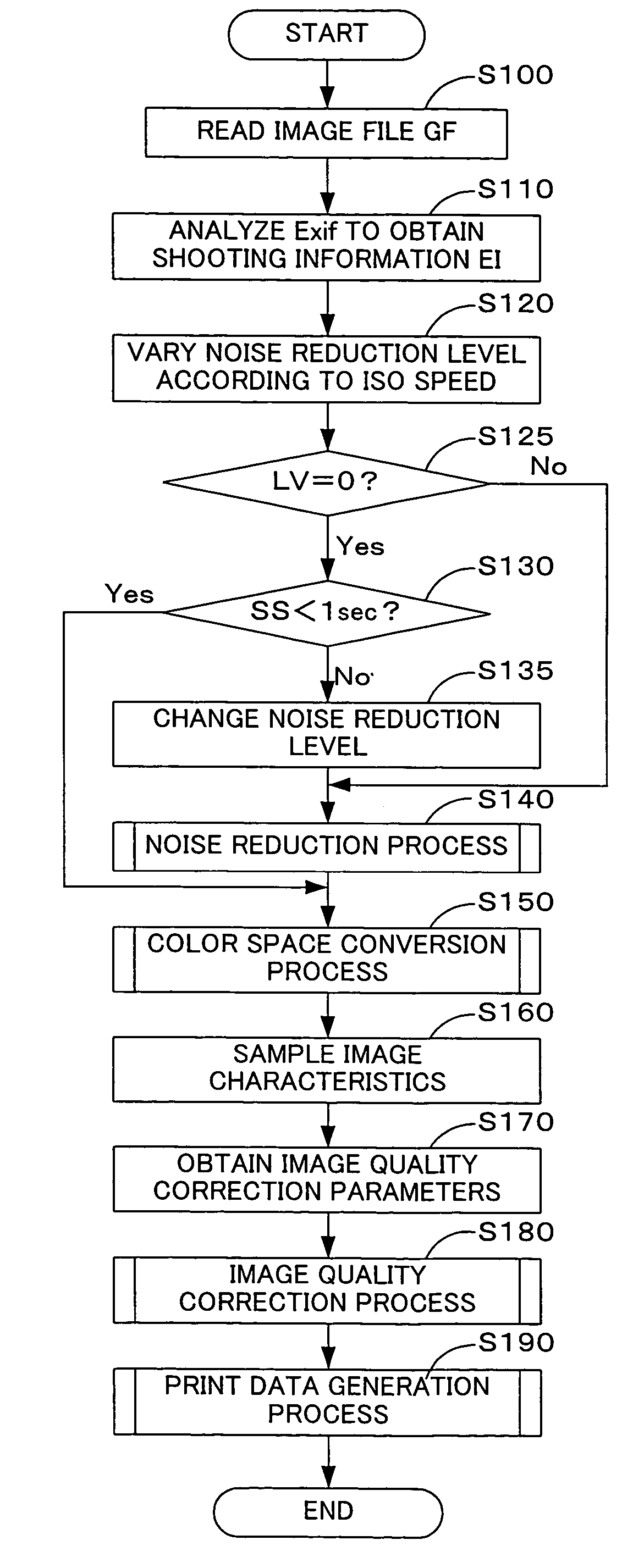
[0043]A series of image processing executed by the personal computer 20 in a first embodiment is discussed below with reference to FIGS. 4 through 6. FIG. 4 is a flowchart showing a main image processing routine executed by the personal computer 20 in the first embodiment. FIG. 5 is a flowchart showing a noise reduction routine executed by the personal computer 20. FIG. 6 is a flowchart showing a print data generation routine executed by the personal computer 20.
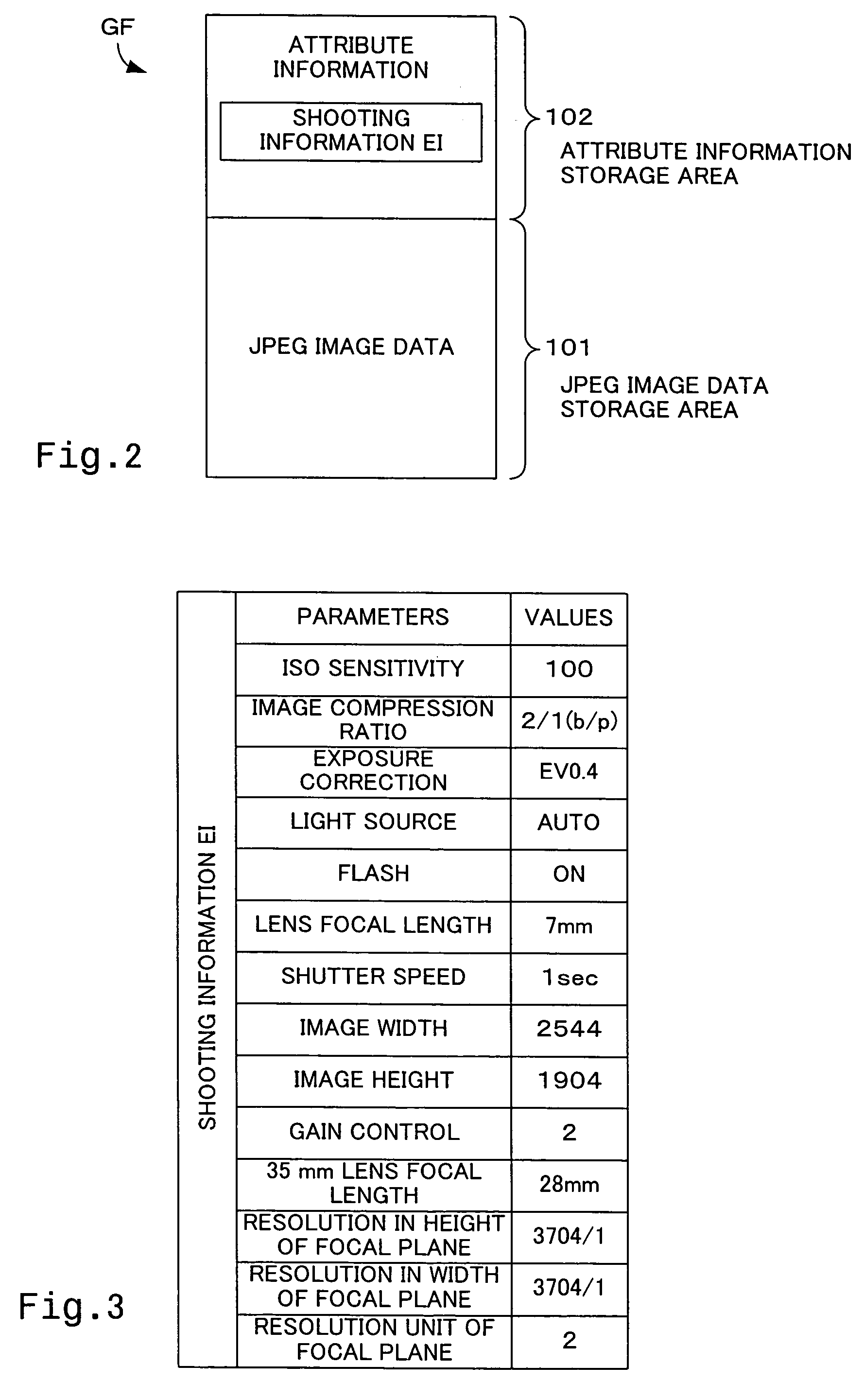
[0044]The CPU 200 of the personal computer 20 starts the image processing routine when the memory card MC is inserted into the slot 250 or when the connector cable CV linked with the DSC 12 on the other end is connected with the input output terminal 255. The CPU 200 first reads an image file GF from the memory card MC via the slot 250 or through the connector cable CV and temporarily registers the read-out image file GF into the RAM 210 (step S100). The image data GD stored here are YCbCr data. The CPU 200 then analyzes the...
second embodiment
[0070]The procedure of the first embodiment determines the noise reduction level according to the ISO speed. When the noise reduction level is described in the image processing control information GI stored in an Exif file, the described noise reduction level may be set to the original noise reduction level LV.
[0071]In this case, the noise reduction level may be changed as described with reference to FIG. 7. FIG. 7 is a flowchart showing a main image processing routine executed by the personal computer 20 in another embodiment. FIG. 8 is a map representing a relation between the noise reduction level LV and the filter size R. The construction of an image processing system used for the second embodiment is identical with the construction of the image processing system 10 of the first embodiment. The respective constituents of the image processing system are thus expressed by like numerals and symbols and are not described specifically. The processing of step S400 and the processing o...
third embodiment
[0077]A series of image processing executed by the personal computer 20 in a third embodiment is described with reference to FIG. 9. FIG. 9 is a flowchart showing a main image processing routine executed by the personal computer 20 in the third embodiment. The construction of an image processing system used for the third embodiment is identical with the construction of the image processing system 10 of the first embodiment. The respective constituents of the image processing system are thus expressed by like numerals and symbols and are not described specifically.
[0078]The image processing of the third embodiment determines the noise reduction level according to the level of gain control (gain control amount), in place of the ISO speed. The gain control amount is an application amount (level) of a gain control parameter on the sensitivity of shooting and represents an amplification amount or an attenuation amount (a sensitizing amount or a desensitizing amount) of an image signal ge...
PUM
 Abstract
Description
Claims
Application Information