Method and system for wind-harnessed battery charging in a locomotive

a technology of wind-harnessed batteries and locomotives, which is applied in the direction of machines/engines, braking components, electric generator control, etc., to achieve the effects of reducing the frequency of battery charging (by the engine), reducing the number and/or duration of engine starts, and slowing down the charging process

Active Publication Date: 2011-02-15
GE GLOBAL SOURCING LLC
View PDF23 Cites 12 Cited by
  • Summary
  • Abstract
  • Description
  • Claims
  • Application Information

AI Technical Summary

Benefits of technology

[0003]Methods and systems are provided for generating electrical energy in a vehicle having at least one airflow device coupled to an electric machine. In one embodiment, the method comprises generating electrical energy at the electric machine, said electric machine being driven by an ambient airflow interacting with the airflow device; and delivering at least some of the harnessed energy to at least an electrical component of the locomotive. The electrical energy generated may be used for charging a system electrical energy storage device, such as a battery, in the vehicle. In this way, energy may be harnessed from ambient airflow through the airflow device, thereby charging the battery and reducing the number and / or duration of engine starts to maintain the battery charge. In another example, the harnessed energy (e.g., the electrical energy generated by the electric machine) may be delivered to an electrical component of the vehicle (e.g., a locomotive), such as to power an electrical load including lights, electronic controllers, etc.
[0004]In one embodiment, naturally flowing airstreams may run through the radiator fans and other component blowers of the stationary locomotive, or other vehicle, causing the blades to rotate. By harnessing the kinetic energy produced by ambient airflow through these components, with an airflow control device and the electric machine, the system battery may be slowly trickle charged. In this manner, the requisite frequency of battery charging (by the engine) may be reduced. The consequent reduction in recurrence of engine start-up and shutdown procedures, while the locomotive is in a stand-by mode of operation, may allow improvement in the engine performance (such as fuel economy, emissions, and noise) and reduced component degradation.

Problems solved by technology

However, many of these components continue to operate even when the locomotive is in a stand-by mode of operation, where the engine may be shutdown and the locomotive is stationary.

Method used


Image

  • Method and system for wind-harnessed battery charging in a locomotive
  • Method and system for wind-harnessed battery charging in a locomotive
  • Method and system for wind-harnessed battery charging in a locomotive

Examples


Embodiment Construction

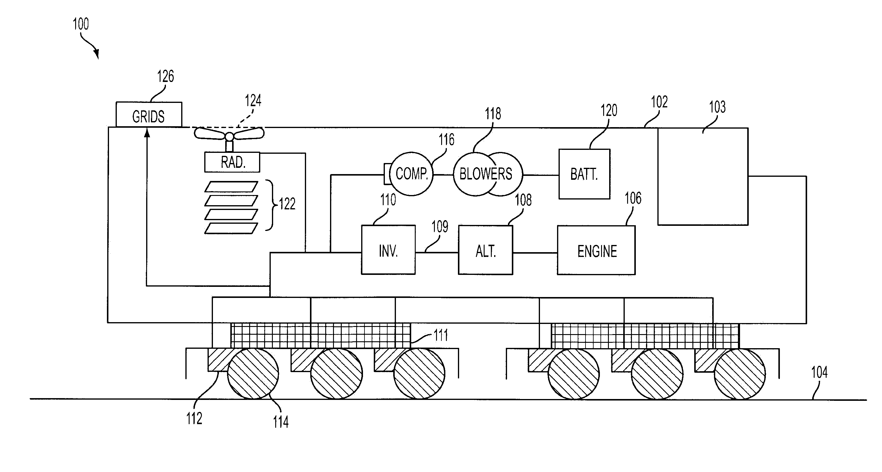
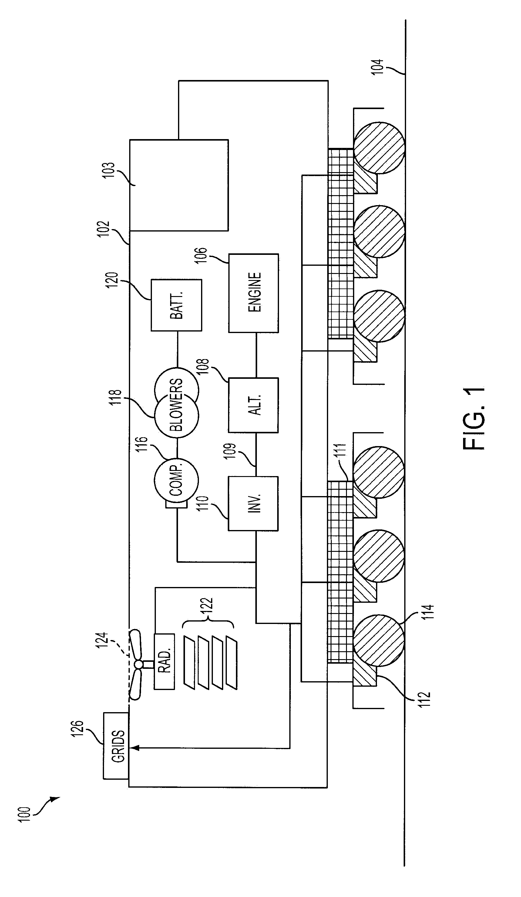
[0013]FIG. 1 is a block diagram of an example locomotive vehicle system 100 (hereafter referred to as “locomotive 100”), configured to run on track 104. As depicted herein, in one example, the locomotive is a diesel electric vehicle operating a diesel engine 106 located within a main engine housing 102. However, in alternate embodiments of locomotive 100, alternate engine configurations may be employed, such as a gasoline engine or a bio diesel or natural gas engine, for example. Locomotive operating crew and electronic components involved in locomotive systems control and management may be housed within a locomotive cab 103.

[0014]The diesel engine generates a torque that is transmitted to an alternator 108 along a drive shaft (not shown). The generated torque is used by alternator 108 to generate electricity for subsequent propagation of the vehicle. Locomotive engine 106 may be run at a constant speed, thereby generating a constant horsepower (hp) output. It will be appreciated th...


PUM


Abstract

Systems and methods are described for generating electrical energy and / or charging a system electrical energy storage device in a vehicle, such as a locomotive. The vehicle includes at least one airflow device coupled to an electric machine. In one example, the method includes, generating electrical energy at the electric machine, said machine being driven by an ambient air flow interacting with the airflow device; and delivering at least some of the harnessed energy to an electrical component of the locomotive. The harnessed energy may be delivered to an electrical load, or delivered to the system electrical energy storage device to charge the device, or combinations thereof.

Description

BACKGROUND[0001]Locomotives have electronic components such as lights, on-board monitoring systems comprising microprocessors and display systems, and other related electronic elements. The power to operate these components is provided by a system battery that is charged by the running locomotive engine. However, many of these components continue to operate even when the locomotive is in a stand-by mode of operation, where the engine may be shutdown and the locomotive is stationary.[0002]Accordingly, during a stand-by mode of operation, as may occur when a locomotive is parked on a siding for a long term, the engine is periodically operated until the battery is re-charged, after which time the engine is shutdown. When the battery charge has dissipated, the engine is again started, and the charging procedure is repeated. Such operation enables the various electronic components to be maintained active during the entire stand-by mode of operation.BRIEF DESCRIPTION OF THE INVENTION[0003...

Claims


Application Information

Patent Timeline
Patent Type & Authority Patents(United States)
IPC IPC(8): B60K16/00B61C17/04
CPCB60L11/02B60L11/18B60L15/2009H02J7/1415B60L8/006H02J7/1438Y02T10/70Y02T10/7083Y02T10/90B60L2200/26Y02T10/7275Y02T10/7005B60L50/10Y02T10/64Y02T10/7072Y02T10/72
Inventor KUMAR, AJITH KUTTANNAIR
Owner GE GLOBAL SOURCING LLC
Why Eureka
Try Eureka