Fan blade with integral diffuser section and tip turbine blade section for a tip turbine engine

a technology of tip turbine engine and diffuser, which is applied in the direction of liquid fuel engine, vessel construction, marine propulsion, etc., can solve the problems of increasing the cost of a tip turbine engine, reducing the efficiency of the tip turbine engine, so as to reduce the leakage between adjacent blade platforms , the effect of easy manufacturing and assembly

Active Publication Date: 2011-02-15
RTX CORP
View PDF149 Cites 5 Cited by
  • Summary
  • Abstract
  • Description
  • Claims
  • Application Information

AI Technical Summary

Benefits of technology

[0012]By forming the turbine directly to fan blades, leakage between adjacent blade platforms is minimized which increases engine efficiency. Manufacturing and assembly is also readily facilitated.
[0013]The present invention therefore provides an assembly arrangement for a fan-turbine rotor assembly which is relatively inexpensive to manufacture yet provides a high degree of reliability.

Problems solved by technology

The axial flow relationship results in a relatively complicated elongated engine structure of considerable longitudinal length relative to the engine diameter.
This elongated shape may complicate or prevent packaging of the engine into particular applications.
A large percentage of the expense associated with a tip turbine engine is the manufacture of the fan-turbine rotor assembly and the integration of the turbine blades with the fan blades.

Method used


Image

  • Fan blade with integral diffuser section and tip turbine blade section for a tip turbine engine
  • Fan blade with integral diffuser section and tip turbine blade section for a tip turbine engine
  • Fan blade with integral diffuser section and tip turbine blade section for a tip turbine engine

Examples


Embodiment Construction

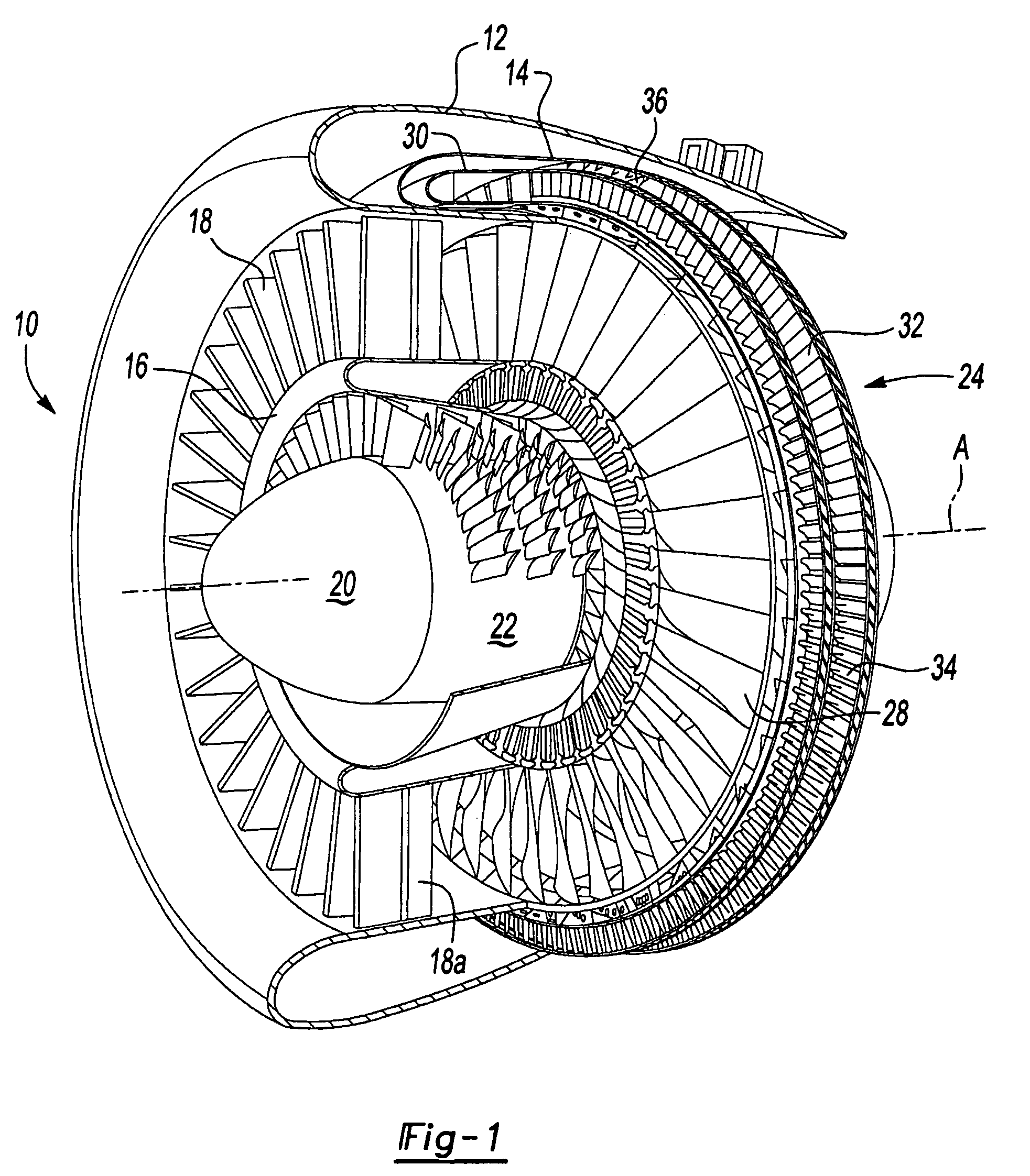
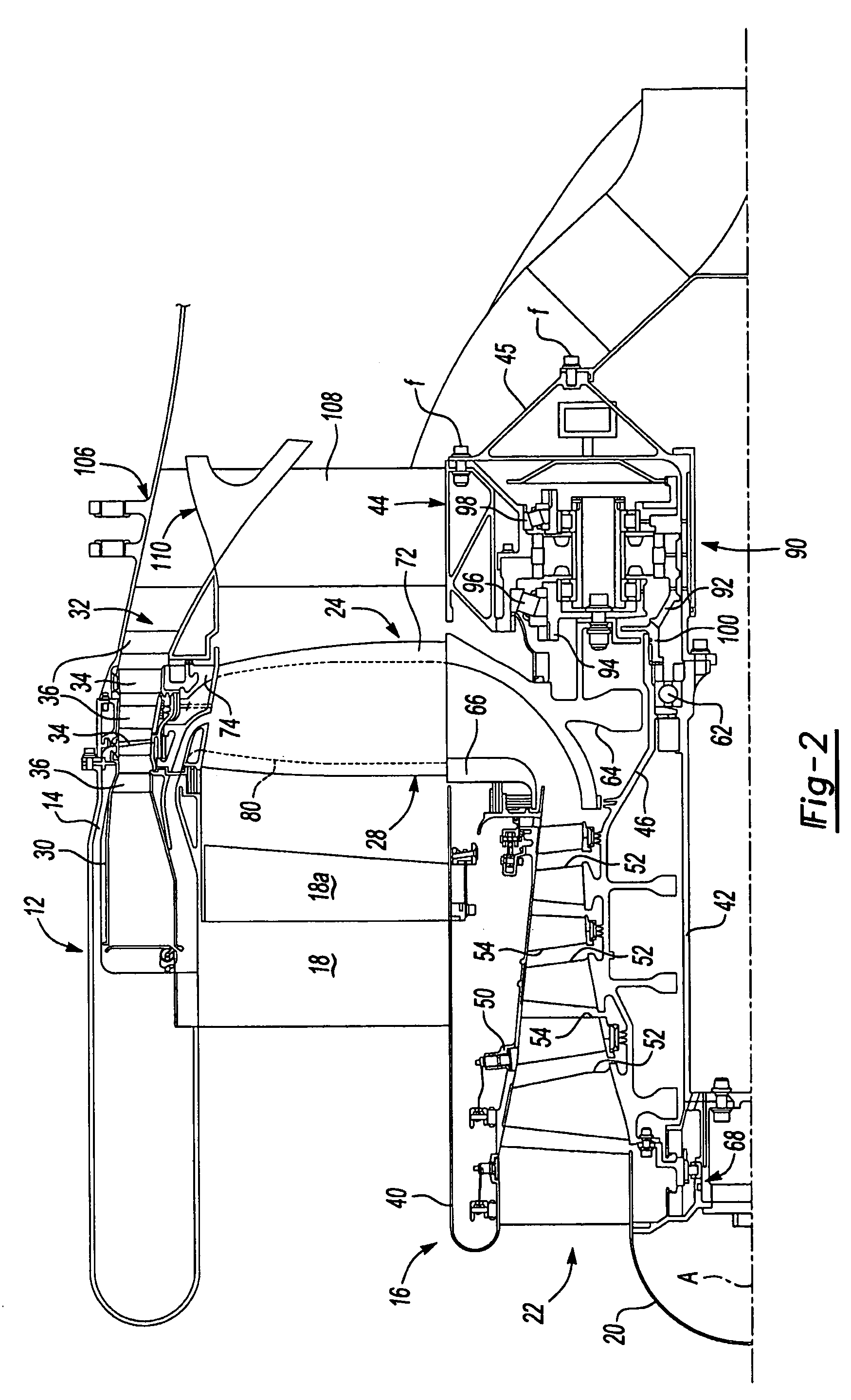
[0030]FIG. 1 illustrates a general perspective partial sectional view of a tip turbine engine type gas turbine engine 10. The engine 10 includes an outer nacelle 12, a nonrotatable static outer support structure 14 and a nonrotatable static inner support structure 16. A multitude of fan inlet guide vanes 18 are mounted between the static outer support structure 14 and the static inner support structure 16. Each inlet guide vane preferably includes a variable trailing edge 18A.

[0031]A nose cone 20 is preferably located along the engine centerline A to direct airflow into an axial compressor 22 adjacent thereto. The axial compressor 22 is mounted about the engine centerline A behind the nose cone 20.

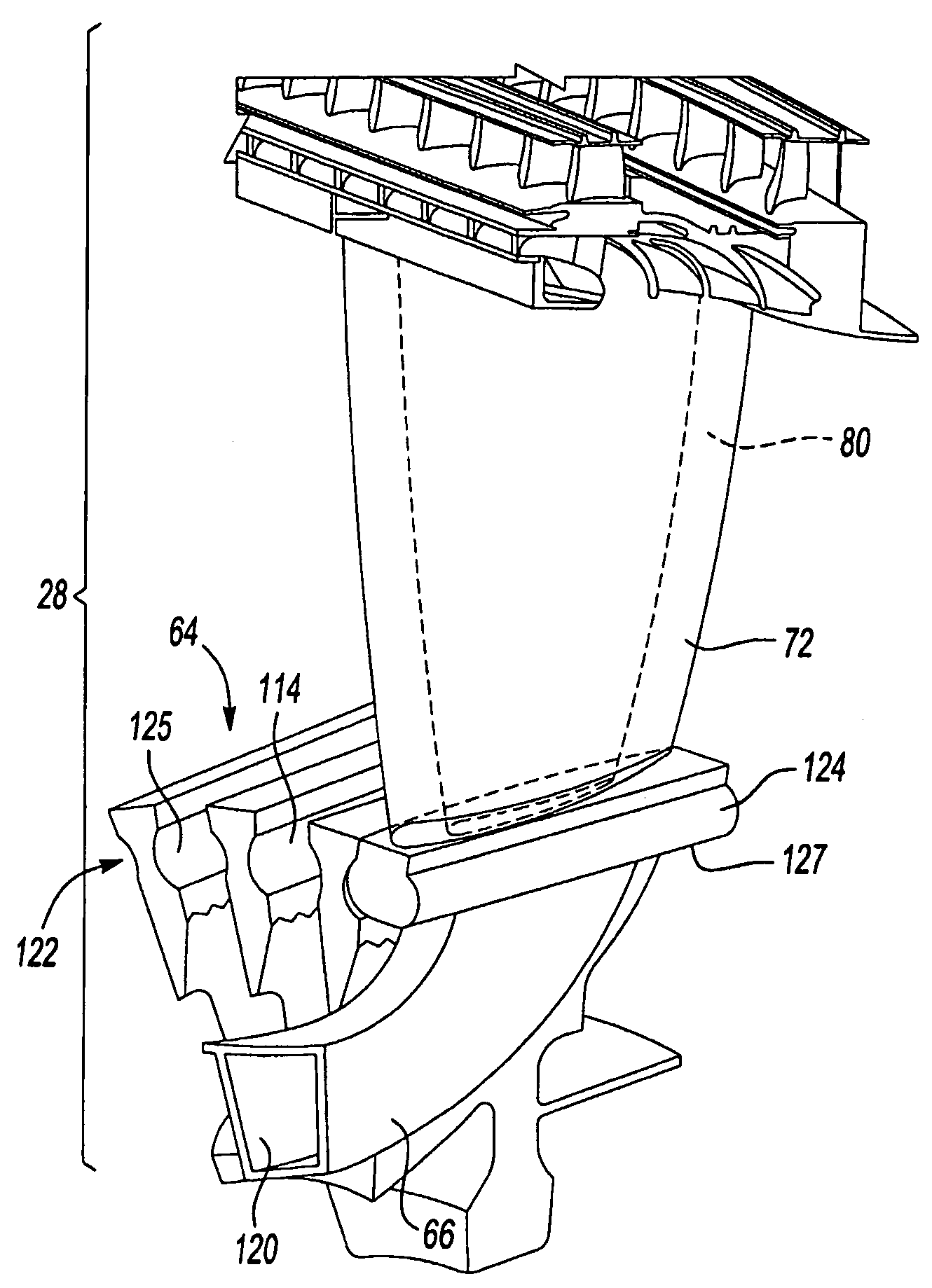
[0032]A fan-turbine rotor assembly 24 is mounted for rotation about the engine centerline A aft of the axial compressor 22. The fan-turbine rotor assembly 24 includes a multitude of hollow fan blades 28 to provide internal, centrifugal compression of the compressed airflow from the axial c...


PUM


Abstract

A fan-turbine rotor assembly for a tip turbine engine includes an outer periphery scalloped by a multitude of elongated openings which define an inducer receipt section to receive an inducer section and a hollow fan blade section. Each fan blade section includes a turbine section which extends from a diffuser section.

Description

[0001]This invention was made with government support under Contract No.: F33657-03-C-2044. The government therefore has certain rights in this invention.BACKGROUND OF THE INVENTION[0002]The present invention relates to a tip turbine engine, and more particularly to a fan-turbine rotor assembly which provides a fan blade with a tip turbine segment formed thereto.[0003]An aircraft gas turbine engine of the conventional turbofan type generally includes a forward bypass fan, a compressor, a combustor, and an aft turbine all located along a common longitudinal axis. A compressor and a turbine of the engine are interconnected by a shaft. The compressor is rotatably driven to compress air entering the combustor to a relatively high pressure. This pressurized air is then mixed with fuel in a combustor and ignited to form a high energy gas stream. The gas stream flows axially aft to rotatably drive the turbine which rotatably drives the compressor through the shaft. The gas stream is also r...

Claims


Application Information

Patent Timeline
Patent Type & Authority Patents(United States)
IPC IPC(8): F01D5/18F01D5/22F02K3/077F02K3/04
CPCF01D1/023F01D1/06F01D5/022F01D5/147F01D5/30F01D5/3007Y02T50/672Y02T50/60
Inventor SUCIU, GABRIEL L.NORRIS, JAMES W.NORDEEN, CRAIG A.MERRY, BRIAN
Owner RTX CORP
Why Eureka
Try Eureka