Temperature compensated power detector

a technology of power detector and temperature compensation, which is applied in the direction of transmission monitoring, control circuit for distortion reduction, electrical apparatus, etc., can solve the problems of limiting the application of power detectors in electronic circuits, affecting the performance of portable radio sets, etc., and achieves low power consumption and good dynamic range.

Active Publication Date: 2011-02-15
SKYWORKS SOLUTIONS INC
View PDF5 Cites 7 Cited by
  • Summary
  • Abstract
  • Description
  • Claims
  • Application Information

AI Technical Summary

Benefits of technology

[0011]Another object of the present invention is to provide a temperature-compensated power detector with a relatively good dynamic range.
[0013]Yet another object of the present invention is to provide a temperature-compensated power detector with low power consumption.

Problems solved by technology

The variations in the output power level may affect the performance of the portable radio set, or may disturb other radio sets operating in its proximity.
This may limit the application of power detectors in electronic circuits, especially if variations in the output power level, as compared to the temperature, need to be tracked.
However, one or more of the methods to temperature-compensate a power detector needs elaborate circuitry, requiring space and power, to provide sufficient temperature compensation.

Method used


Image

  • Temperature compensated power detector
  • Temperature compensated power detector
  • Temperature compensated power detector

Examples


Embodiment Construction

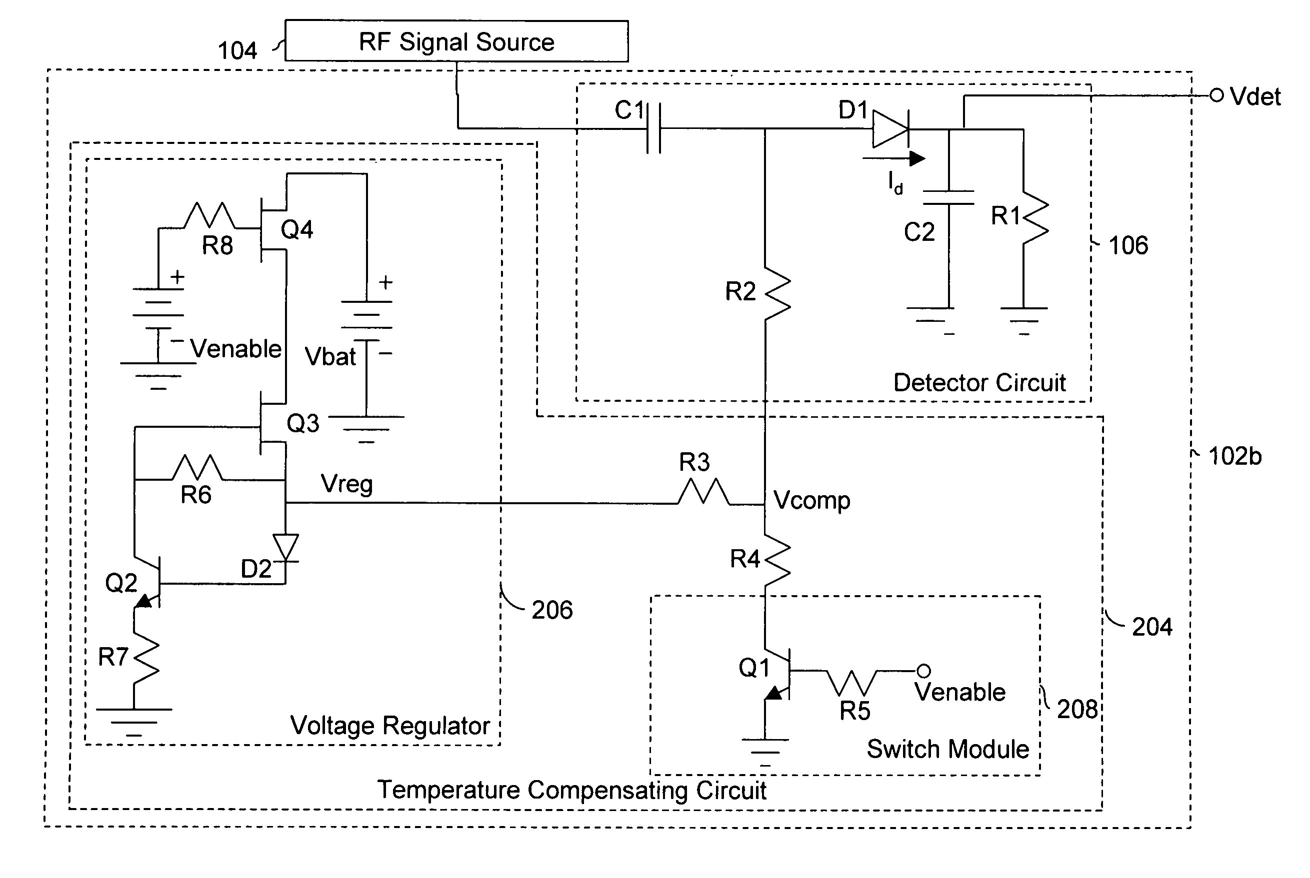
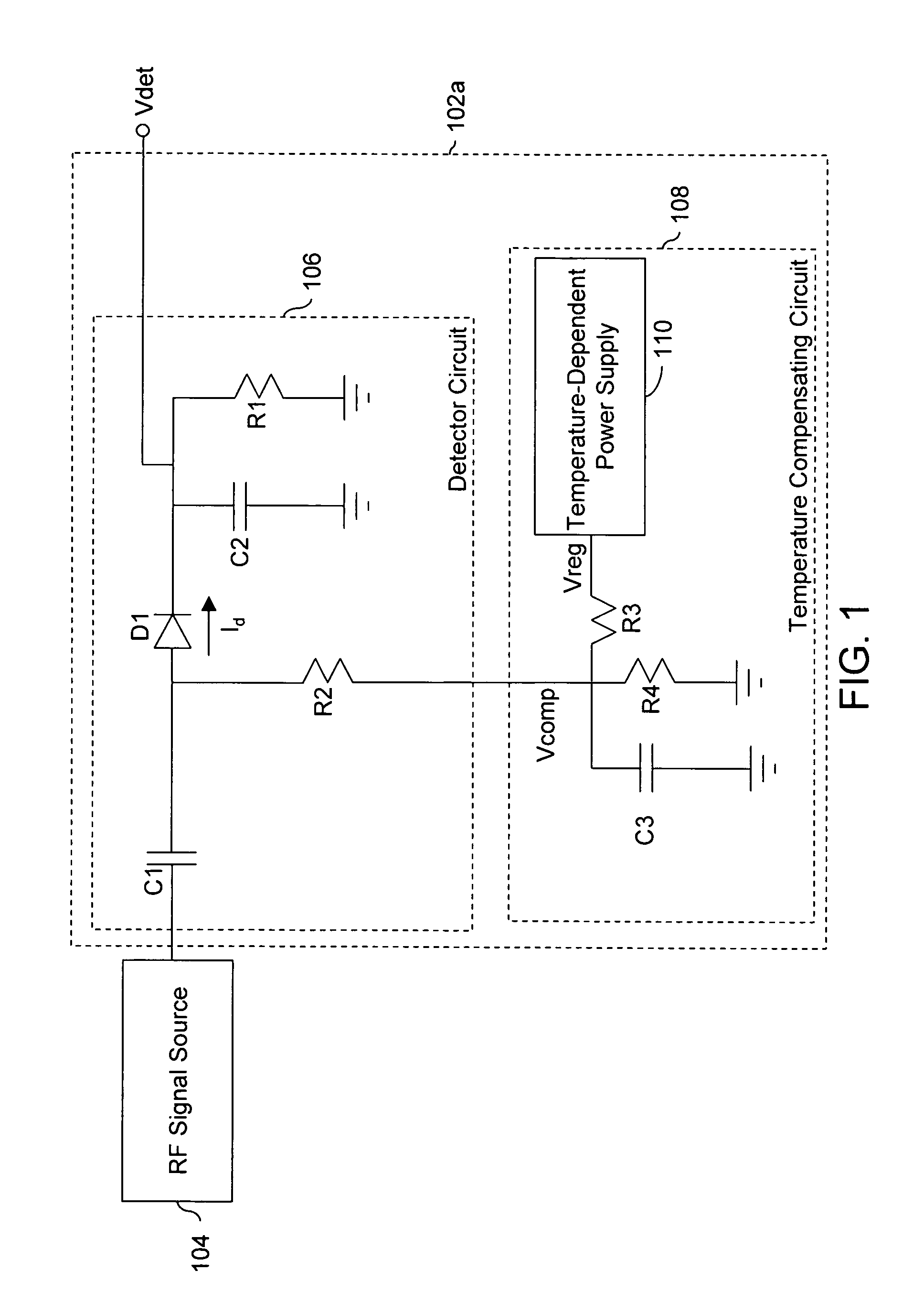
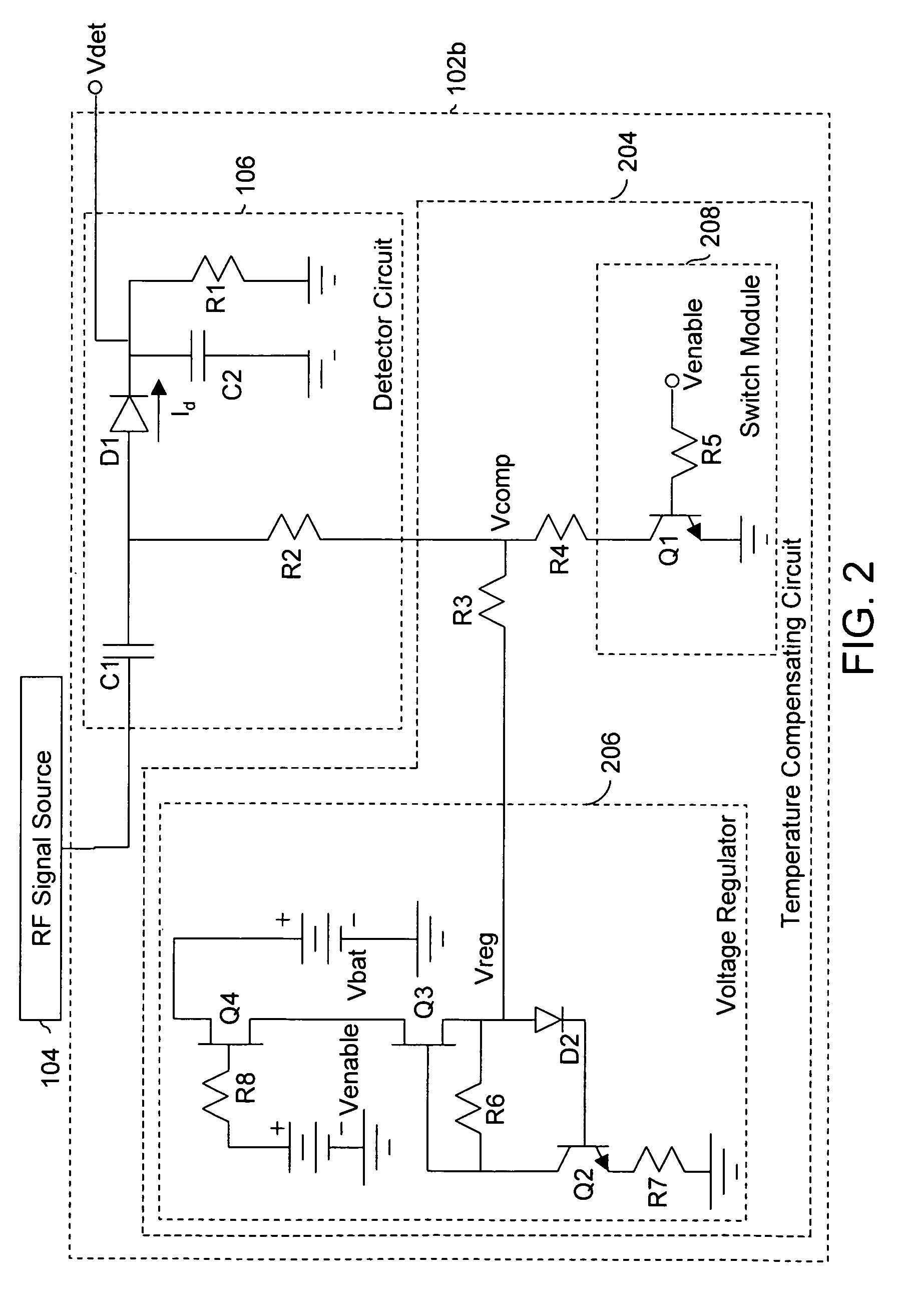
[0019]Various embodiments of the invention provide a temperature-compensated power detector for a Radio Frequency (RF) application. The temperature-compensated power detector includes a detector circuit and a temperature compensating circuit. The detector circuit detects the power level of an input RF signal and provides an output voltage that corresponds to the power level. The temperature compensating circuit ensures that the output voltage provided by the detector circuit is independent of changes in temperature, thereby temperature-compensating the detector circuit.

[0020]FIG. 1 is a schematic representation of a circuit diagram of a temperature-compensated power detector 102a, in accordance with an embodiment of the invention. Temperature-compensated power detector 102a is hereinafter referred to as power detector 102a. FIG. 1 includes a power detector 102a and an RF signal source 104. Power detector 102a includes a detector circuit 106 and a temperature compensating circuit 108...


PUM


Abstract

A temperature-compensated power detector for detecting variations in the power level of an RF signal. The temperature-compensated power detector includes a detector circuit and a temperature compensating circuit. The detector circuit detects the power level of an RF signal and provides an output voltage that corresponds to the power level of the RF signal. The temperature compensating circuit ensures that the output voltage of the temperature-compensated power detector is independent of changes in the temperature.

Description

RELATED APPLICATIONS[0001]This application is related to the following application which is hereby incorporated by reference as if set forth in full in this specification: co-pending U.S. patent application Ser. No. 11 / 329,449, entitled “Compact Voltage Regulator”, filed on Jan. 11, 2006.BACKGROUND OF THE INVENTION[0002]The present invention relates to power detectors. More specifically, it relates to a temperature-compensated power detector, which may be integrated into wireless communication devices. Examples of wireless communication devices include portable radio sets, mobile phones, Personal Digital Assistants (PDAs), wireless data-processing units, and the like.[0003]For example, in a portable radio set, the output power level may vary with frequency, temperature and power supply. It may also vary from one portable radio set to another. The variations in the output power level may affect the performance of the portable radio set, or may disturb other radio sets operating in it...

Claims


Application Information

Patent Timeline
Patent Type & Authority Patents(United States)
IPC IPC(8): H03C1/62
CPCH03G1/04G01R21/10H04B2001/0416
Inventor LIWINSKI, HENRY
Owner SKYWORKS SOLUTIONS INC
Why Eureka
Try Eureka