Dual arm robot

a robot and arm technology, applied in the field of dual arm robots, can solve the problem that the robot cannot be used in a vacuum transport module built per semi-mesc standards

Inactive Publication Date: 2011-02-22
BOOKS AUTOMATION US LLC
View PDF8 Cites 97 Cited by
  • Summary
  • Abstract
  • Description
  • Claims
  • Application Information

AI Technical Summary

Benefits of technology

[0012]The present invention provides a dual arm robot in which two arms each have a set of joint/link pairs that, in conjunction with an actuator assembly, define at least three degrees of freedom to provide independent horizontal translation (extension and retraction) and rotation of a distal

Problems solved by technology

This robot, however, cannot be used in a vacuum transport module built per SEMI MESC standards, because the isolation valves of such a vacuum transport module are too

Method used


Image

  • Dual arm robot
  • Dual arm robot
  • Dual arm robot

Examples


Embodiment Construction

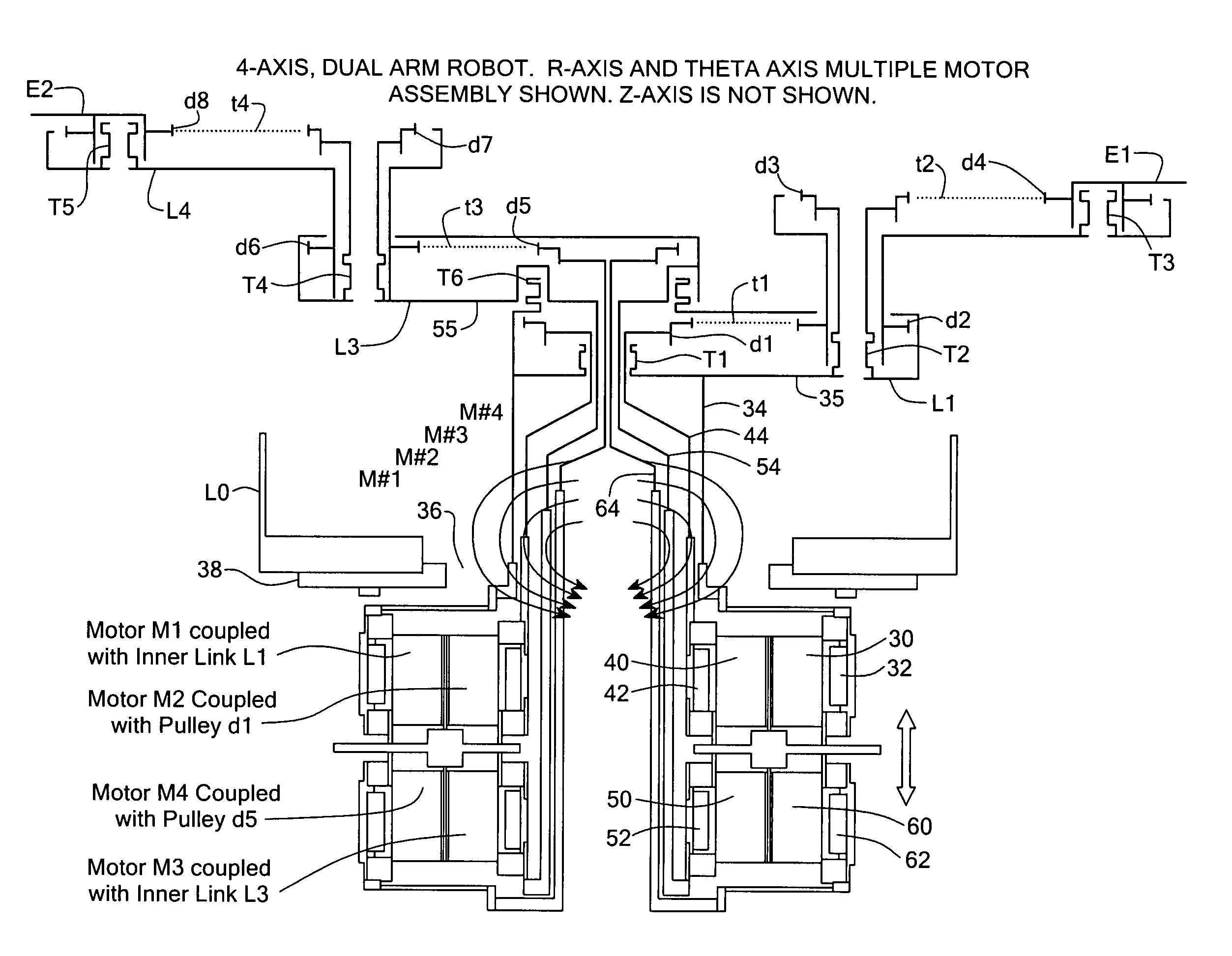
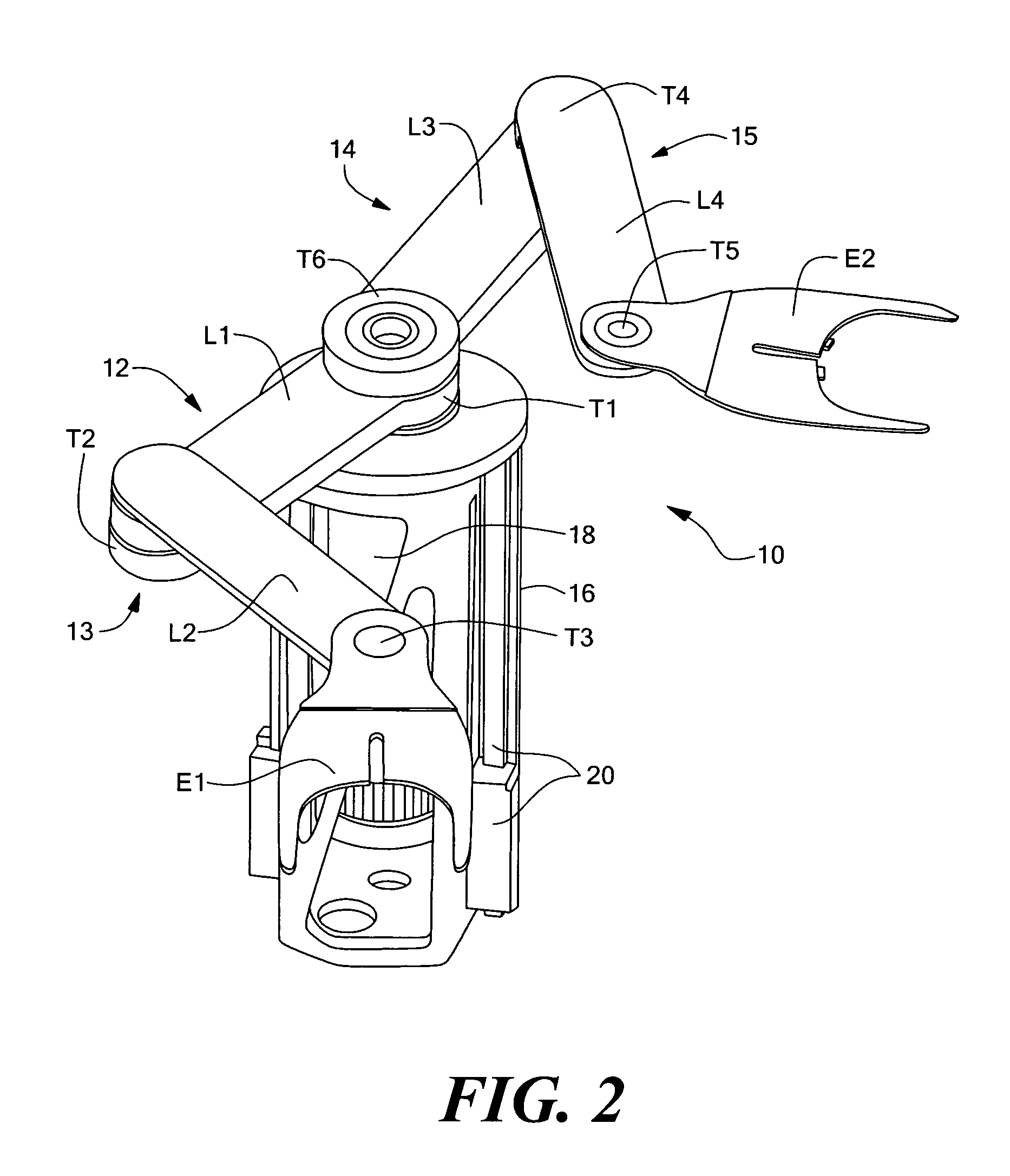
[0125]The present invention relates to a dual arm, cylindrical coordinate robot assembly, and more particularly to the manipulator, the system of links and joints that cooperate to position a pair of end effectors, for such a robot assembly.

[0126]For purposes of describing the present invention, the manipulator can be described as a mechanical assembly and broken down into major linkages, minor linkages (wrist components), and the end effector. The major linkages are the set of joint-link pairs that position the manipulator in space. Usually, the major linkages are the first three sets of joint-link pairs. The first joint-link pair includes a prismatic joint (e.g., a linear bearing) and a link (e.g., a carriage) that allows for vertical displacement of the tool. The second joint-link pair includes a revolute joint (e.g., a radial ball bearing) and a link (e.g., an inner link). The third joint-link pair includes a revolute joint (e.g., a radial ball bearing) and a link (e.g., an oute...


PUM


Abstract

A dual arm robot assembly has two arms each having a set of joint/link pairs that, in conjunction with an actuator assembly, define at least three degrees of freedom to provide independent horizontal translation and rotation of a distalmost link. A vertical motion mechanism is also provided.

Description

CROSS REFERENCE TO RELATED APPLICATIONS[0001]Applicant claims priority under 35 U.S.C. §119(e) to prior U.S. provisional applications Ser. Nos. 60 / 378,983, 60 / 379,095 and 60 / 379,063; all filed May 9, 2002, the disclosures of which are incorporated herein by reference.STATEMENT REGARDING FEDERALLY SPONSORED RESEARCH OR DEVELOPMENT[0002]N / ABACKGROUND OF THE INVENTION[0003]Robots are used to perform many tasks in the semiconductor industry, such as the automated handling of substrate media or other objects. In the semiconductor industry, typical media and other objects include individual silicon wafers or wafer carriers, flat panel displays, and hard disk media. Robots may be used for handling media in, for example, wafer processing cluster tools, wafer inspection equipment, metrology equipment, and equipment for hard disk thin film deposition, and in transferring media between production equipment and automated material handling systems in semiconductor factories. Robots may be used i...

Claims


Application Information

Patent Timeline
IPC IPC(8): B25J18/02B25J9/04H01L21/677
CPCB25J9/042B25J9/044H01L21/67742B25J9/126H01L21/67739Y10S901/17Y10T74/20341B25J15/0246Y10T74/20317Y10T74/20323Y10S901/23B25J9/043
Inventor KREMERMAN, IZYA
Owner BOOKS AUTOMATION US LLC
Why Eureka
Try Eureka