Power control using at least 540 degrees of phase

a phase control and power control technology, applied in the direction of pulse technique, automatic control of ignition, instruments, etc., can solve the problems of conventional phase control and cycle theft, the control of the power provided to the device, and the need for power sufficient to maintain the fuser temperature within a desired range, so as to minimize signal artifacts, high power factor, and fine control of the power received

Inactive Publication Date: 2011-02-22
XEROX CORP
View PDF9 Cites 13 Cited by
  • Summary
  • Abstract
  • Description
  • Claims
  • Application Information

AI Technical Summary

Benefits of technology

[0003]Dropping out portions of the sinusoidal AC power signal is conventionally accomplished by phase control or cycle stealing methods. Conventional phase control acts over one half-cycle (180 degrees of the cycle) in a manner such as shown in FIG. 1. An essentially infinitesimal amount of a phase can be dropped, thereby enabling fine tuning of the amount of power reaching a device. Conventional cycle stealing enables the dropping of whole half cycles in a sequence of N half cycles as shown in FIG. 2. In conventional cycle stealing, each of the drops commences only at the zero crossing points, thereby offering only N different power levels. In order to avoid imparting a DC-offset, conventional cycle stealing utilizes an odd number of half-cycles and typically uses patterns of 3-half cycles, or 540 degrees.
[0007]For devices which require high power factors, such as modern high speed printers, it is desired to provide a means for modulating the AC power signal to provide fine control of the power received by the device, minimize signal artifacts such as harmonics and flicker, while providing a relatively high power factor to ensure efficient use of the power supplied. Also, for energy conservation purposes, high power factors are desired.

Problems solved by technology

A frequent issue in providing electric power to a device is control of the power provided to the device.
During non-imaging but machine-on periods, only power sufficient to maintain fuser temperature within a desired range is required.
Both conventional phase control and cycle stealing present problems depending upon particular applications.
For conventional phase control, problems arise because the switching, or dropping of the signal, occurs every 180 degrees at points other than the zero crossing points.
With conventional phase control, these limits are easily exceeded.
For conventional cycle stealing, several problems similarly result.
Conventional cycle stealing is accordingly relatively inflexible and does not permit fine tuning of delivered power.
Secondly, some modes of cycle stealing (particularly as N is made larger) cause voltage variation in the mains, which, in turn causes some light sources to appear to flicker as detected by the human eye.
The result is that when an “on” half cycle resumes, the filament has significantly less resistance, and an in-rush spike in current is created and a voltage fluctuation is sent down the mains.
However, flicker problems persist.
The result, as explained above, is a cooling of lamp filaments resulting in lowered resistance which, in turn, results in increases inrush current and flicker.
As described above, however, methods of varying power by cycle stealing, phase control, pattern switching, chopping peak voltages, or similar methods all reduce power received by the device by dropping a portion of the AC signal.
Since the full AC signal (kVA) is undiminished, such reduced actual load power (kW) used by the device reduces the power factor.

Method used


Image

  • Power control using at least 540 degrees of phase
  • Power control using at least 540 degrees of phase
  • Power control using at least 540 degrees of phase

Examples


Embodiment Construction

[0019]For a general understanding of the present invention, reference is made to the drawings. In the drawings, like reference numerals have been used throughout to designate identical elements.

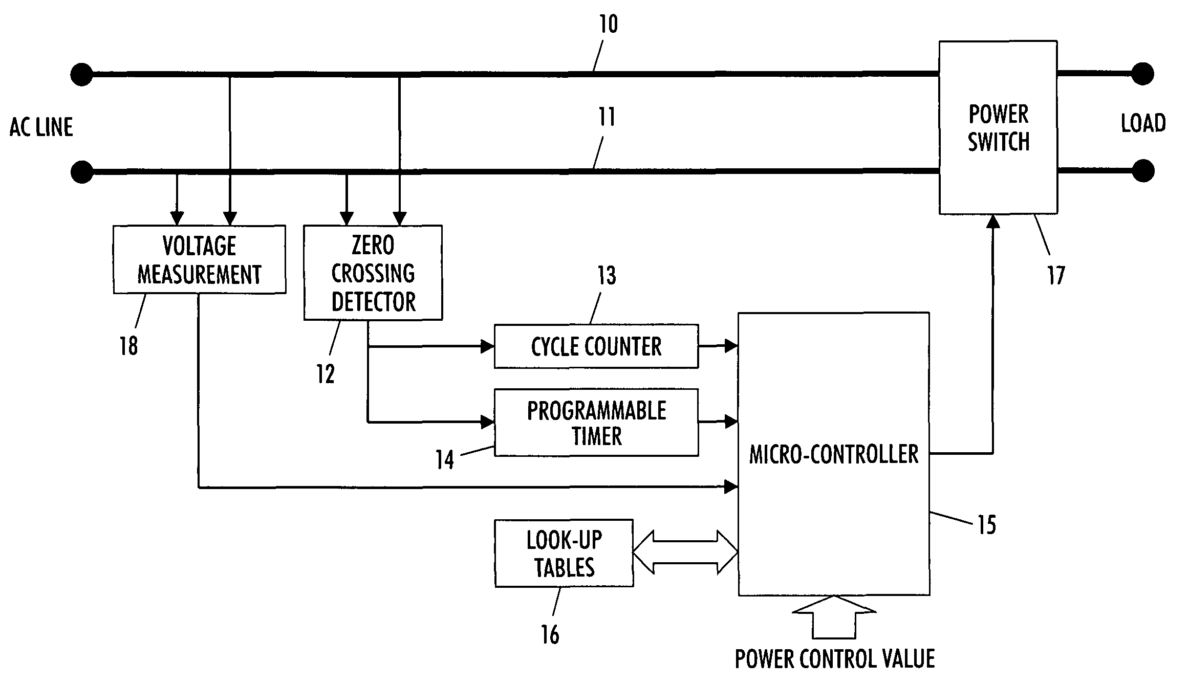
[0020]An exemplary electronic system comprising one embodiment of the present invention is a multifunctional printer with print, copy, scan, and fax services. Such multifunctional printers are well known in the art and may comprise print engines based upon ink jet, electrostatography, and other imaging devices. The general principles of electrostatographic imaging are well known to many skilled in the art as exemplified by electrophotography. Generally, the process of electrophotographic reproduction is initiated by substantially uniformly charging a photoreceptive member, followed by exposing a light image of an original document thereon. Exposing the charged photoreceptive member to a light image discharges a photoconductive surface layer in areas corresponding to non-image areas in the ori...


PUM

PropertyMeasurementUnit
phase angleaaaaaaaaaa
RMS voltageaaaaaaaaaa

Abstract

A circuit and method for generating an electrical alternating current power signal in which the alternating current signal is dropped once at a non-zero crossing point in every 540 plus N degrees, where N is a non-negative number. This manner of controlling power to a device enables wide ranges of power control while generating acceptable levels of power line harmonics and while conforming to existing international regulations governing voltage variations.

Description

BACKGROUND AND SUMMARY[0001]The present invention relates to selection of AC power phases and waveform control in order to select a waveform that optimizes delivered power within acceptable power and flicker limits.[0002]A frequent issue in providing electric power to a device is control of the power provided to the device. Voltage can be decreased with simple resistors. Transformers can modulate between increased voltage and decreased current or vice versa. For devices that require varying amounts of power depending upon application, however, manipulation of the AC current waveform is a preferred method. Devices such as the heating lamps inside fuser rolls of electrostatographic printers are such an application. For fast warm-up cycles and during periods in which much heat is drawn from a fuser because of rapid printing speeds, full power drawn from an AC power source is desired. During non-imaging but machine-on periods, only power sufficient to maintain fuser temperature within a...

Claims


Application Information

Patent Timeline
Patent Type & Authority Patents(United States)
IPC IPC(8): G05F5/00
CPCH02M5/2576
Inventor THURLOW, BARRY J.STEVENSON, DUNCAN I.POTTER, SCOTT M.COOPER, JOHN W D.
Owner XEROX CORP
Why Eureka
Try Eureka