Switching power supply circuit
a power supply circuit and power supply technology, applied in the direction of electric variable regulation, process and machine control, instruments, etc., can solve problems such as leakage of magnetic flux, and achieve the effects of improving saturation characteristic, instantaneous increase of power consumption, and power supply performance to a dynamic load
- Summary
- Abstract
- Description
- Claims
- Application Information
AI Technical Summary
Benefits of technology
Problems solved by technology
Method used
Image
Examples
first embodiment
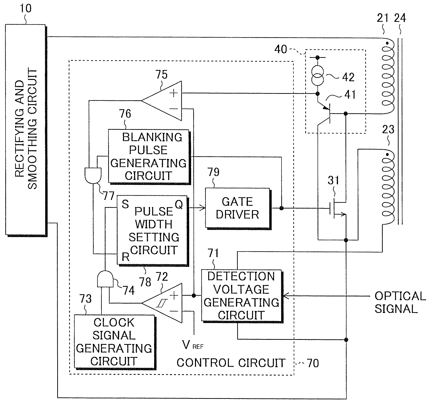
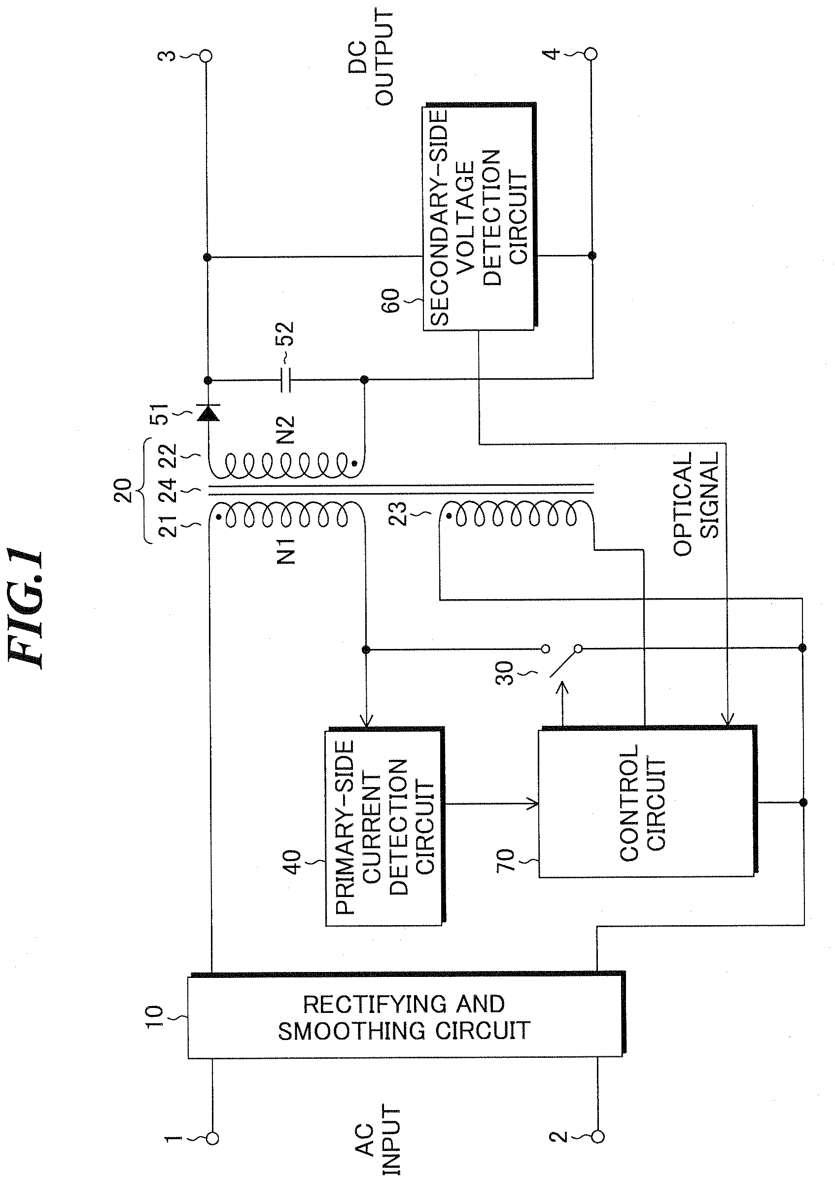
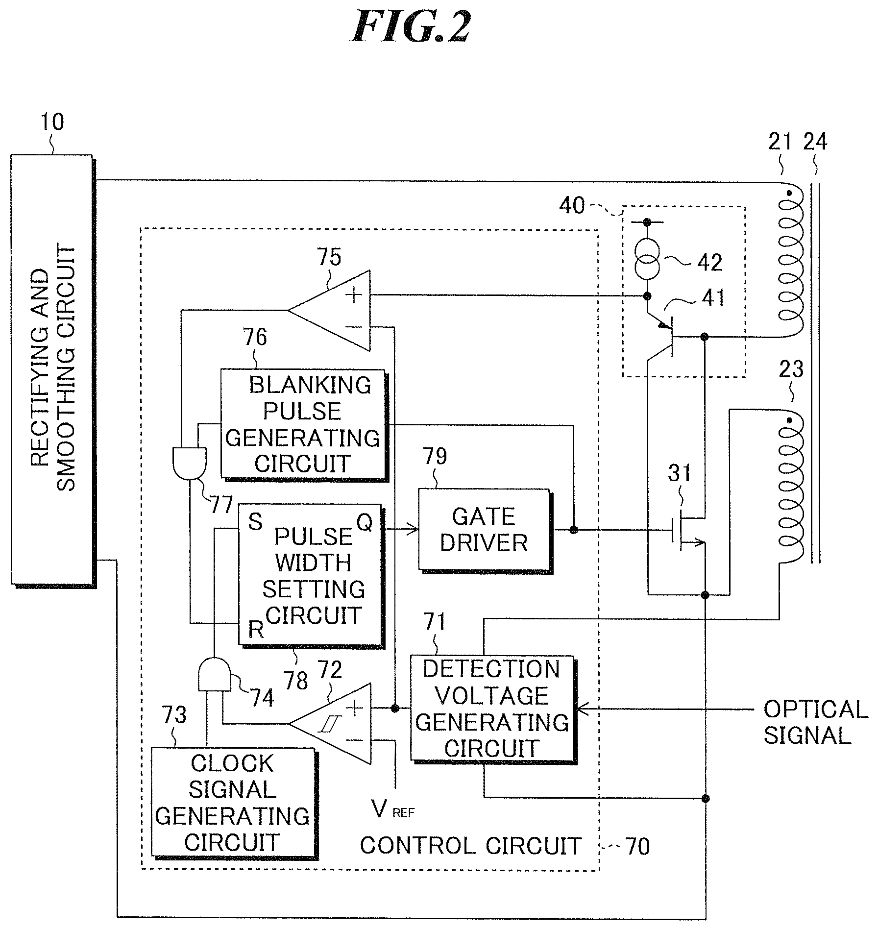
[0039]FIG. 1 shows a configuration of a switching power supply circuit according to the present invention. This switching power supply circuit has a rectifying and smoothing circuit 10 connected to input terminals 1 and 2 for an alternating-current power supply voltage, a transformer 20 for stepping up or stepping down the alternating-current voltage at the primary side and outputting it to the secondary side, a switching element 30 series-connected to a primary-side winding 21 of the transformer, for flowing current through the primary-side winding 21 of the transformer according to a pulsive drive signal, and a primary-side current detection circuit 40 for detecting the current flowing through the primary-side winding 21 of the transformer.
[0040]Further, the switching power supply circuit has a diode51 for half-wave rectifying a voltage generated in a secondary-side winding 22 of the transformer, a capacitor 52 for smoothing the rectified voltage, a secondary-side voltage detectio...
second embodiment
[0078]FIG. 6 specifically shows the configuration of the control circuit and so on in the present invention. In the embodiment, a control circuit 90 judges whether or not the current flowing in the MOSFET 31 exceeds the rated current and generates the drive signal to be applied to the gate of the MOSFET 31 in accordance therewith. Here, the rated current refers to the magnitude of the drain current that the MOSFET can stably perform the steady operation, and determined in advance based on the AC input voltage of the switching power supply circuit, the MOSFET standard, or the like.
[0079]The control circuit 90 includes a comparator 91 and a mask signal generating circuit 92 in place of the comparator 72 as shown in FIG. 2. The comparator 91 compares the magnitude of the primary side current detected by the primary-side current detection circuit 40 with a preset voltage VP set according to the rated current, and outputs a comparison signal representing the comparison result. The mask s...
third embodiment
[0088]Next, the present invention will be explained.
[0089]FIG. 8 shows a configuration of a switching power supply circuit according to the third embodiment of the present invention. This switching power supply circuit has a rectifying and smoothing circuit 10 connected to input terminals 1 and 2 for an alternating-current power supply voltage, a transformer 20 for stepping up or stepping down the alternating-current voltage at the primary side and outputs it to the secondary side, a switching element 30 series-connected to a primary-side winding 21 of the transformer, for flowing current through the primary-side winding 21 of the transformer according to a pulsive drive signal, and a primary-side current detection circuit 100 for detecting the current flowing through the primary-side winding of the transformer 20.
[0090]Further, the switching power supply circuit has a diode 51 for half-wave rectifying a voltage generated in a secondary-side winding 22 of the transformer, a capacito...
PUM
 Abstract
Description
Claims
Application Information
 - R&D
- Intellectual Property
- Life Sciences
- Materials
- Tech Scout
- Unparalleled Data Quality
- Higher Quality Content
- 60% Fewer Hallucinations
Browse by: Latest US Patents, China's latest patents, Technical Efficacy Thesaurus, Application Domain, Technology Topic, Popular Technical Reports.
© 2025 PatSnap. All rights reserved.Legal|Privacy policy|Modern Slavery Act Transparency Statement|Sitemap|About US| Contact US: help@patsnap.com


