
Method and apparatus for treating wound using negative pressure therapy

a negative pressure and wound technology, applied in the field of medical devices, can solve the problems of not considering the generation of negative pressure vacuum compression, and achieve the effects of reducing healthcare costs, improving skin protection and skin care, and improving patient convenience and ease of us

Inactive Publication Date: 2011-03-01
THERANOVA LLC
View PDF26 Cites 68 Cited by
  • Summary
  • Abstract
  • Description
  • Claims
  • Application Information

AI Technical Summary

Benefits of technology

[0025]The present invention creates and maintains negative pressure vacuum via an active pump mechanism or a self-powered pump (through the use of mobility and weight bearing) for the control of edema and / or acceleration of healing of limb wounds. Devices have utilized positive pressure compression in various forms to facilitate the return of interstitial fluid (or edema) from limbs to the heart, but devices have not been contemplated, prior to this invention, to provide circumferential vacuum therapy to a non-amputated limb. The innovation of present invention involves the use of a flexible stocking-type device that employs the creation and maintenance of negative pressure to reduce edema, improve venous return, and help protect skin.
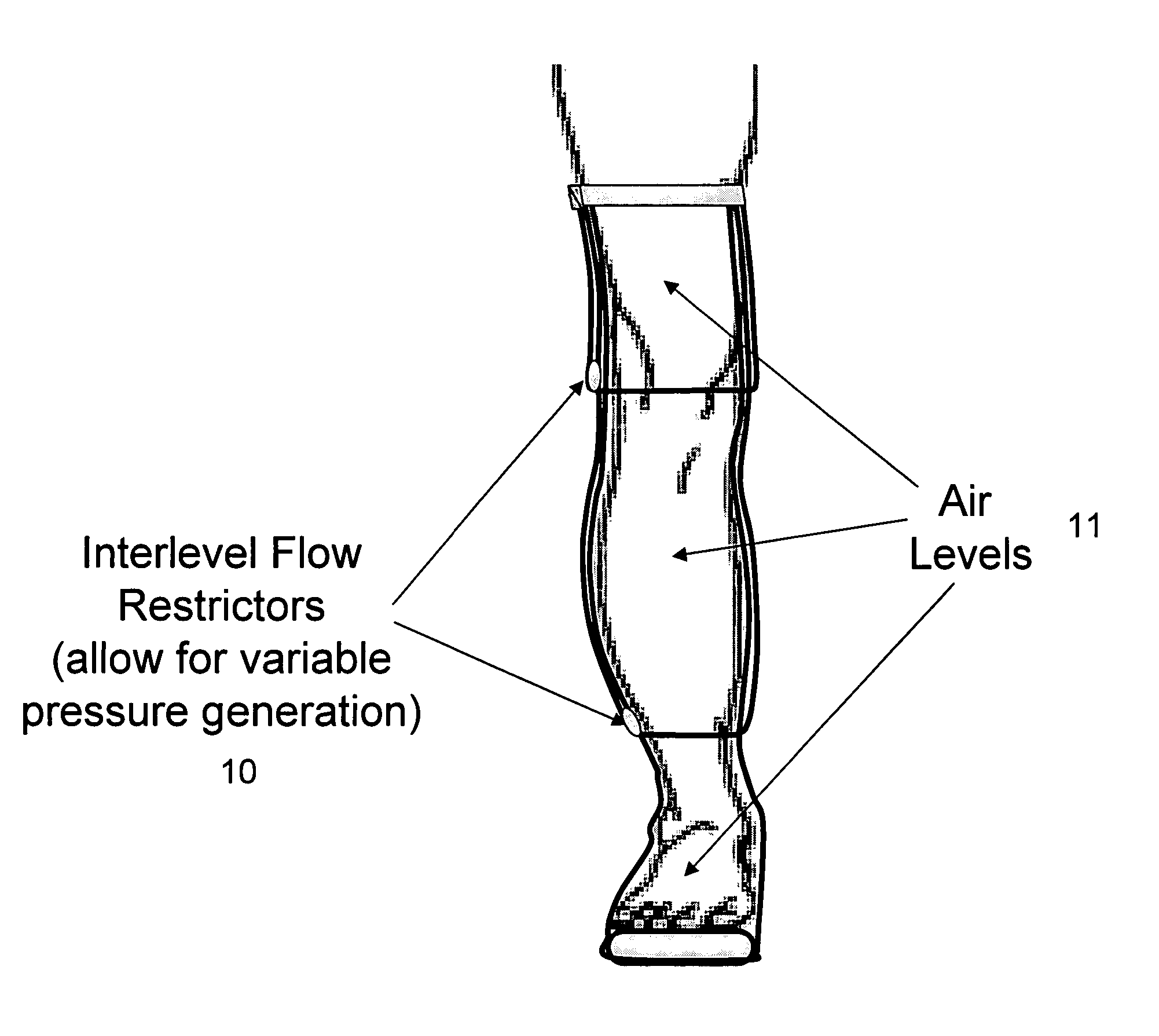
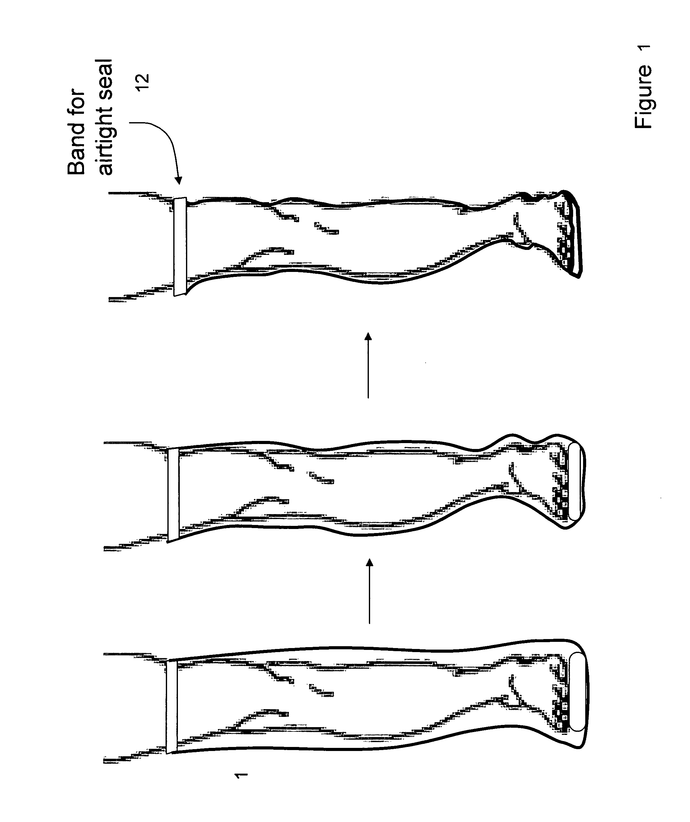
[0026]The Dynamic Vacuum Compression Appliance consists of a sealed region, and a vacuum generating mechanism. The sealed region can be composed of urethane, silicone or any flexible material that is able to form a tubular shell capable of forming an air seal and surrounding some or all of a limb. The sealed region can be of sufficient length to cover all or part of the leg. The sealed region contains a band, e.g. an elastic or Velcro band, which can provide a relatively airtight seal to allow for vacuum generation in the leg. The sealed region may optionally contain longitudinal air support channels to allow for the transmission of vacuum from the vacuum pump to the top of the garment in a reliable manner avoiding air pockets. Alternatively, the sealed region may incorporate a pressure-sensitive or open-air influx valve. This air influx valve can allow for the development of pressure gradients in the leg or the slow-release of vacuum with a decline in the rate of vacuum pump activation. The development of pressure gradients can also be achieved through the use of air levels incorporated into the garment. These air levels can provide air pockets with variable access to vacuum, either using pressure-sensitive valves or simple smaller diameter higher resistance tubing such that the vacuum provided at increasing elevation is less than that in the inferior air level. This interlevel flow restriction feature will allow for the “milking of the leg” with activation of the vacuum pump. The air levels can also be used in combination with the air influx valve to provide a dynamic pressure gradient throughout the limb.
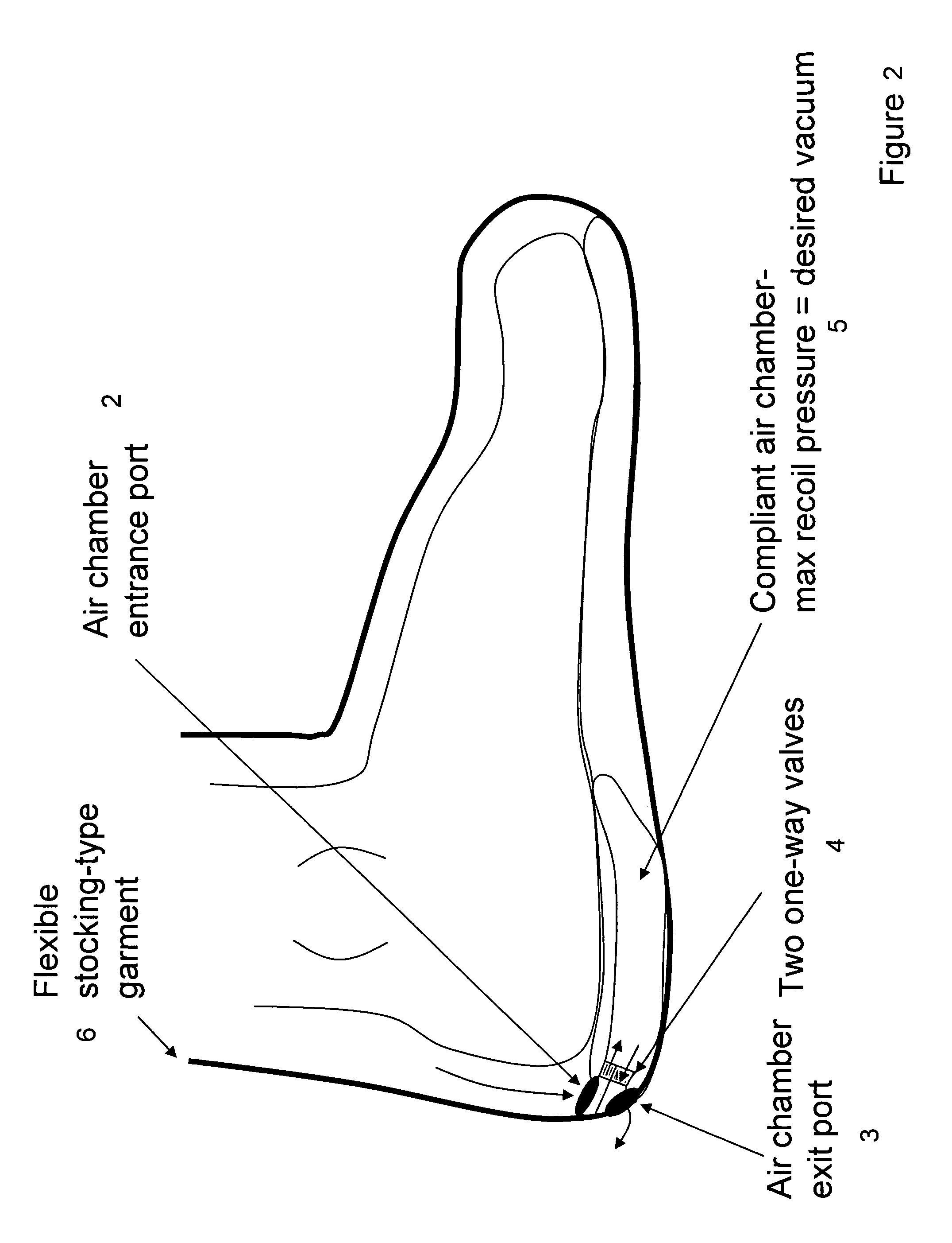
[0027]The vacuum generating mechanism can be incorporated into an insole-like device designed to be placed inside of standard footwear. This component will incorporate a resilient air chamber and two valves or flow restrictors (such as smaller diameter tubing) to channel air out of the garment upon compression of the air chamber by the foot and to allow air to enter the air chamber from the garment with recoil of the air chamber. The recoil and compliance of the air chamber can be tailored such that it will not recoil once a certain vacuum has been established, thus ensuring that the correct negative pressure is achieved. This appliance will thus employ the force generated during normal standing and walking to actively generate vaccum forces and allow air to be evacuated through a one-way check valve. As the negative pressure builds within the stocking, the garment surfaces will draw in around the skin to generate compression for the application of controlled pressure to the limb. This generated compression will then support the superficial venous appliance, helping to reduce edema and aid venous return.
[0030]In an alternative embodiment, the vacuum generating mechanism can be incorporated into a boot (e.g. walking or post-surgical boot). With this embodiment, the air compliant chamber, valves, tubing, and other components could be built into the structure of the boot into which the compression garment would fit. This embodiment would facilitate the accommodation of limbs of various sizes, wounds of various types, and would obviate the need for designing special shoes to interface with the compression garment.
[0034]The competitive advantages of the Dynamic Vacuum Compression Appliance include: 1) Improved patient convenience and ease of use, 2) Improved skin protection and care of skin, and 3) Reduction of healthcare costs with the prevention of complications (such as venous ulcers) and decreased requirement for custom fitting of compression garments.

Problems solved by technology

While this device has taken the step to incorporate self-powered compression into the design of this appliance, the generation of negative pressure vacuum compression is not contemplated.

Method used


Image

  • Method and apparatus for treating wound using negative pressure therapy
  • Method and apparatus for treating wound using negative pressure therapy
  • Method and apparatus for treating wound using negative pressure therapy

Examples


Embodiment Construction

Device

Dynamic Vacuum Compression Appliance

[0067]Indications for Use:[0068]1) Limb edema, with associated causes including chronic venous insufficiency, congestive heart failure, lymphedema, and other related conditions[0069]2) Prevention of fluid accumulation, and[0070]3) Treatment of skin ulceration

[0071]Methods for Use:[0072]1) A patient with edema of the lower extremity, for example, will place the flexible stocking-type garment on the affected limb(s),[0073]2) A tight seal will be formed at the proximal end of the stocking-type garment. This seal can be achieved in any number of different manners, including the placement of a band around the top of the stocking,[0074]3) The stocking-type garment will be coupled to an insole-like device designed to be placed inside of standard footwear. This component will incorporate a resilient air chamber and two valves or flow restrictors (such as smaller diameter tubing) to channel air out of the garment upon compression of the air chamber b...


PUM


Abstract

Devices that employ external compression stocking-type garments in the treatment of edema, chronic wounds, deep venous thrombosis prevention or claudication all share a number of significant limitations. These include the frequent need for custom fitting to assure an appropriate fit, vigilant maintenance to assure a continued “good fit,” limited compliance with proper use by patients and difficulty of application. There is a large body of evidence demonstrating that patients often decline to wear the compressive stockings as prescribed or in the form that would be most beneficial because they find these devices to be difficult to put on and take off.Building on the limitations of existing therapies, and distilled lessons learned from the field of prosthetics and wound healing, the present invention employs vacuum-assisted negative pressure to provide compression and help pump fluid from the tissues of affected limbs. The device is embodied in the form of a flexible stocking-like garment that will utilize a pumping mechanism to generate negative pressure around the limb and thus create vacuum compression that will mobilize fluid in a limb and increase venous return to the heart. Through the use of a circumferential wrap, the present invention provides a major advance in both the distribution of vacuum and the securing of the device over the limb.

Description

CROSS-REFERENCES TO RELATED APPLICATIONS[0001]This application claims priority to U.S. Provisional Patent Application Ser. No. 60 / 643,145, filed Jan. 12th, 2005. The relevant disclosure of the application cited in this paragraph is hereby incorporated by reference.BACKGROUND OF THE INVENTION[0002]The present invention relates to the field of medical devices, in particular therapeutic intervention devices for the reduction of edema and improvement of venous return to the heart with applications in the field of medicine.[0003]Prior to the present invention, various compression devices have been known in the art for applying compressive pressure to a patient's limbs in order to increase blood flow and return of fluid from a limb.[0004]These compression devices take a number of different forms, including:[0005]1) The SCD (trademark of The Kendall Company), a sequential compression device that provides intermittent pulses of compressed air that sequentially inflate multiple chambers in a...

Claims


Application Information

Patent Timeline
Patent Type & Authority Patents(United States)
IPC IPC(8): A61H7/00A61H23/00A61F13/06A61F13/66
CPCA61H9/005A61H2201/1238A61H2205/10A61H2209/00A61M1/916A61M1/917
Inventor MANGRUM, SHANEBURNETT, DANIEL
Owner THERANOVA LLC
Learn More