Method for manufacturing a reinforced shell for forming component parts for aircraft and shell for component parts for aircraft

a technology for aircraft and components, applied in the field of shell manufacturing, can solve the problems of limited shelf time of pre-repairs, disproportionally high costs, and not-yet-cured components, and achieve the effect of simplifying the manufacture of shells

Inactive Publication Date: 2011-03-01
AIRBUS OPERATIONS GMBH
View PDF28 Cites 23 Cited by
  • Summary
  • Abstract
  • Description
  • Claims
  • Application Information

AI Technical Summary

Benefits of technology

[0014]It is therefore an object of the present invention to avoid the disadvantages of the known processes as described above and to enable a simplified manufacture of shells with a shell skin and stiffening elements.
[0019]In accordance with a preferable embodiment of this method, an adhesive is applied to the connecting elements prior to the curing. This results in a better tolerance compensation between the shell skin and the stiffening elements. Moreover, a mechanically firmer connection between the stiffening elements and the shell skin as well as the connecting elements is achieved. The application of adhesive onto the connecting elements in conjunction with the inventive method is optional. Typically, a sufficiently firm connection of the stiffening elements to the shell skin can be achieved with connecting elements that are partially cured and therefore adaptable and capable of adhesion.
[0020]Due to the fact that the stiffening elements are connected to the shell skin by connecting elements that are cured afterwards, the inventive shell can be manufactured easily. Since the stiffening elements as well as the shell skin is at least partially cured and only the connecting elements need to be cured completely, the means for positioning the connecting elements on the shell skin can be simple. Due to the high inherent stability of the at least partially cured shell skin and the at least partially cured stiffening elements, the necessary positioning means or positioning devices may also be arranged outside the vacuum sack. Regardless of the shell skin and the positioning elements that have already been cured, a tolerance compensation is possible by means of the not-yet-cured connecting elements. Furthermore, with the inventive shell, the still flexible connecting elements allow the placement of stiffening elements in areas of the shell skin that comprise a thickened portion or the like. In this case, the stiffening elements should be provided with recesses.

Problems solved by technology

The shelf-time of prepregs is limited due to continuously occurring cross-linking processes, and is ordinarily only between 10 and 30 days at room temperature.
The main disadvantage of this process is that it requires a very elaborate apparatus for positioning and fixing the stiffening elements relative to the shell skin during the curing process, which leads to disproportionally high costs, in particular in the case of shells of large dimensions for forming complex component parts, such as airfoil wings, for example.
The main disadvantage of this process variant is that the respectively not-yet-cured component, that is, the stiffening elements or the shell skin, for example, is subject to quality fluctuations, that cannot be ignored.
These quality fluctuations may lead in particular to a disadvantageous fiber distribution in the resin matrix, to warping, as well as to pores and trapped air, which is caused primarily by setting movements of the cured component during the curing process.
The disadvantages of this approach include in particular the higher number of necessary processing steps as well as the necessary fitting precision of the stiffening elements, the connecting angle piece and the shell skin, which ordinarily cannot be ensured with shells of larger dimensions.

Method used


Image

  • Method for manufacturing a reinforced shell for forming component parts for aircraft and shell for component parts for aircraft
  • Method for manufacturing a reinforced shell for forming component parts for aircraft and shell for component parts for aircraft
  • Method for manufacturing a reinforced shell for forming component parts for aircraft and shell for component parts for aircraft

Examples


first embodiment

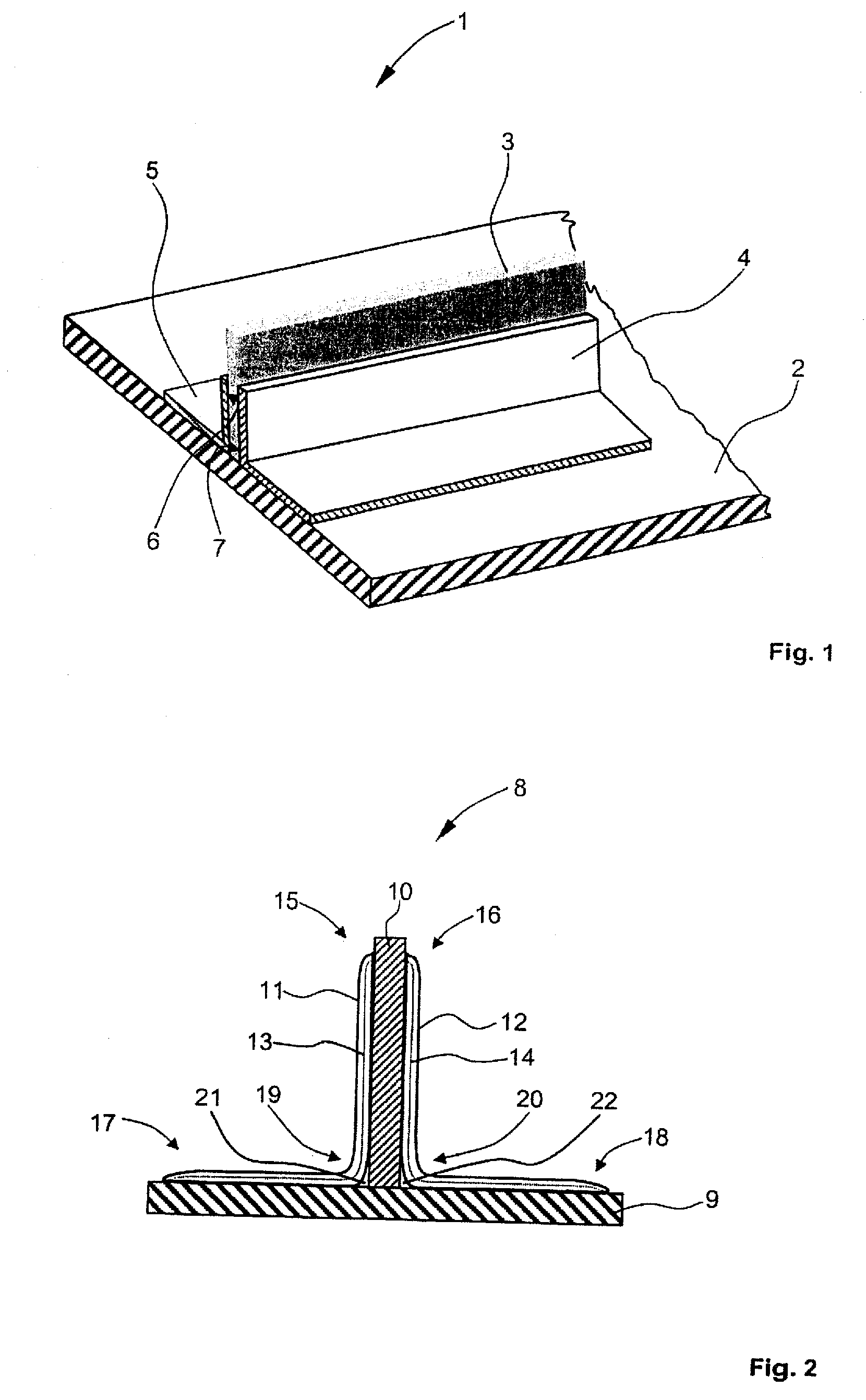
[0025]FIG. 1 shows a partial perspective view of a shell with a stiffening element that has been attached in accordance with the present invention.

[0026]A shell 1 comprises a shell skin 2, a stiffening element 3 as well as connecting elements 4 and 5. As shown in FIG. 1, the stiffening element 3 has a substantially rectangular cross-section. However, the stiffening element 3 may also have other cross-sectional shapes. The connecting elements 4 and 5 are connecting angle pieces with a substantially L-shaped cross-section. The shell skin 2, the stiffening element 3 and the connecting elements 4 and 5 are made of a plurality of semi-finished parts in the form of curable prepregs. The prepregs are carbon fiber reinforced sheet-shaped members, that are soaked or impregnated with a curable epoxy resin. In their non-cured state, virtually any geometric shape can be imparted on the prepregs. Thus, using prepregs as semi-finished parts, shell skins or stiffening elements with L-shaped cross-...

second embodiment

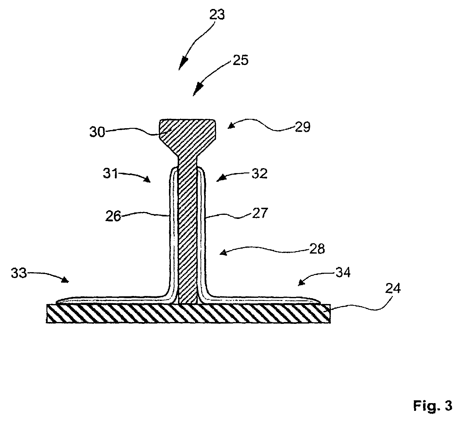
[0043]FIG. 3 shows a partial cross-sectional view of a shell, onto which a stiffening element is placed, in accordance with a

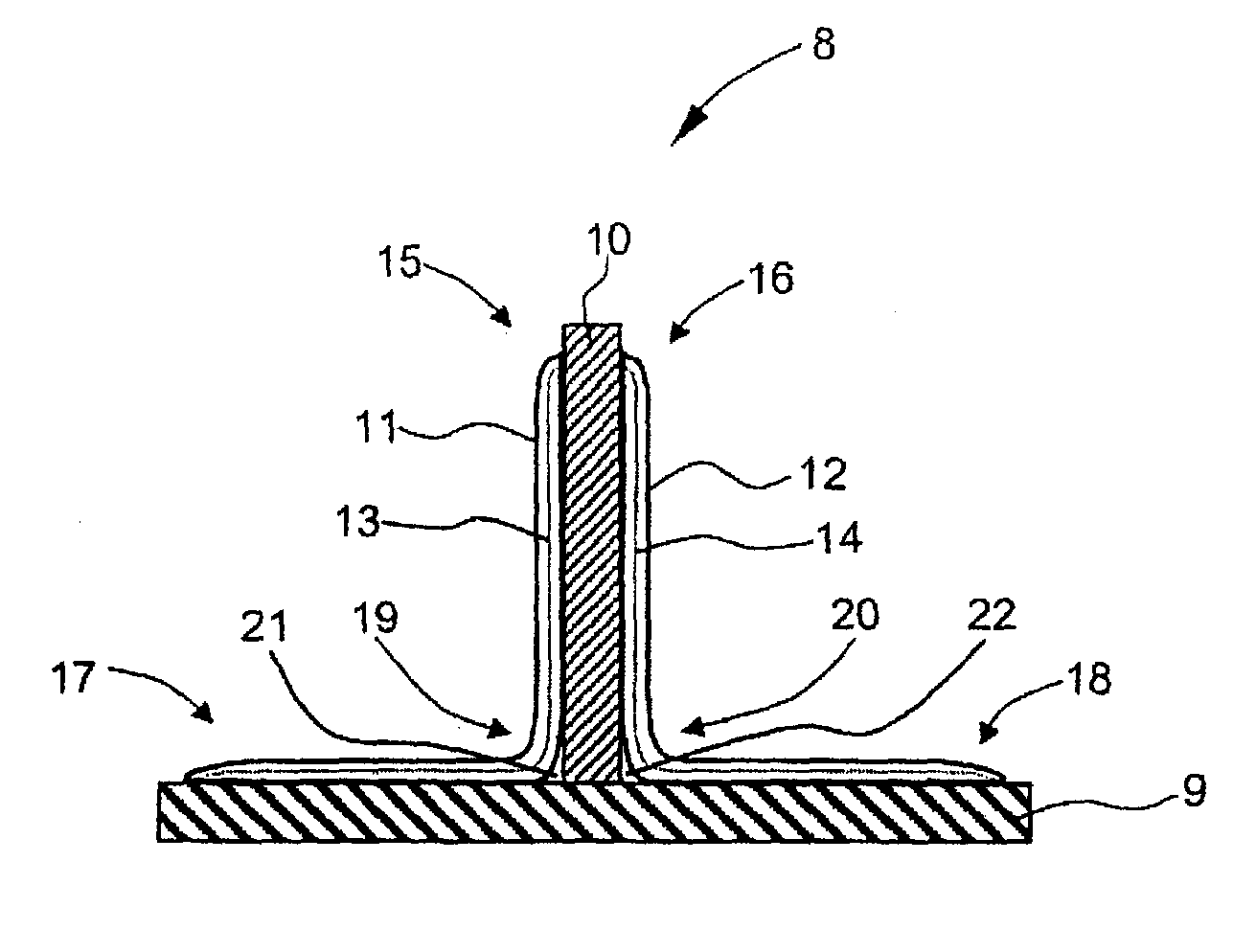
[0044]The shell 23 is provided with a shell skin 24, onto which at least one stiffening element 25 is attached with connecting elements 26 and 27 arranged on either side in accordance with an inventive method. In contrast to the stiffening element 10, the stiffening element 25 does not have a rectangular cross-section. In a lower region 28, the stiffening element 25 has a rectangular shape, whereas in an upper region 29, it is provided with a widening section 30. The widening section 30 enables a higher flexural rigidity of the stiffening element 25. Due to the widening section 30 arranged in the upper region 29, it may be necessary to make the legs 31, 32 shorter than the legs 33, 34 of the connecting elements 26, 29. Other details of FIG. 3 correspond to those shown in FIG. 2, so that their further description has been omitted.

[0045]In accordance with one as...


PUM

PropertyMeasurementUnit
pressuresaaaaaaaaaa
temperatureaaaaaaaaaa

Abstract

The invention concerns a method for manufacturing a shell, in particular a fuselage shell, a wing shell, a horizontal stabilizer shell or a vertical stabilizer shell, that is reinforced with a plurality of stiffening elements, for forming component parts for aircraft with high dimensional stability, wherein the stiffening elements and a shell skin are made with epoxy resin from at least partially cured carbon fiber reinforced semi-finished parts, the method comprising the following steps:positioning the stiffening elements on the shell skin,abutting connecting elements against the shell skin and the stiffening elements, andcuring the connecting elements to form the shell.The invention also concerns a shell, in particular a fuselage shell, a wing shell, a horizontal stabilizer shell or a vertical stabilizer shell, manufactured in accordance with the inventive method.

Description

FIELD OF THE INVENTION[0001]The present invention relates to a method for manufacturing a shell, in particular a fuselage shell, a wing shell, a horizontal stabilizer shell or a vertical stabilizer shell, that is reinforced with a plurality of stiffening elements, for forming component parts for aircraft with high dimensional stability, wherein the stiffening elements and a shell skin are made with epoxy resin from at least partially cured carbon fiber reinforced semi-finished parts.BACKGROUND OF THE INVENTION[0002]Furthermore, the invention relates to a shell, in particular a fuselage shell, a wing shell, a horizontal stabilizer shell or a vertical stabilizer shell, manufactured in accordance with the inventive method, comprising a plurality of stiffening elements applied to a shell skin, for forming component parts for aircraft with high dimensional stability, wherein the stiffening elements and the shell skin are made with epoxy resin from at least partially cured carbon fiber re...

Claims


Application Information

Patent Timeline
Patent Type & Authority Patents(United States)
IPC IPC(8): B29C45/00
CPCB29C65/5071B29C66/112B29C66/114B29C66/43441B29C66/721B29C70/44B29C70/543B29C70/845B64C1/068B64C3/24B29C65/5042B29C35/0227B29C65/483B29K2063/00B29K2307/00B29L2031/3076B29L2031/3082B29L2031/3085B64C2001/0072Y02T50/433B29C65/48B29C66/71B29C66/7212Y02T50/40B29K2307/04
Inventor RAECKERS, BERND
Owner AIRBUS OPERATIONS GMBH
Why Eureka
Try Eureka