
Device for applying at least one surface section of a transfer layer of a transfer film to a web of material and the use thereof

a transfer film and web technology, applied in the direction of drying machine, labelling machine, roll, etc., can solve the problems of inability to achieve reproducibility of pressure, time-consuming and labor-intensive optimization of pressure contact force of pressure rollers, etc., and achieve the effect of rapid optimisation of pressure contact for

Inactive Publication Date: 2011-03-08
LEONHARD KURZ GMBH & CO KG
View PDF19 Cites 2 Cited by
  • Summary
  • Abstract
  • Description
  • Claims
  • Application Information

AI Technical Summary

Benefits of technology

Now the object of the invention is to provide an improved apparatus which permits uncomplicated and in particular rapid optimisation of the pressure contact force of at least one pressure roller against a support roller, and to provide for use thereof.
Preferably the at least one support roller is heated in order to provide for optimum transfer of the transfer layer on to the web of material and to reduce as far as possible the period of time required for satisfactory transfer of the transfer layer on to the web of material. An adhesive layer provided on the transfer layer can be caused to melt by the heat so that a strong adhesive join is established between the web of material and the transfer layer. The fact that a roller cage extends around the heated support roller produces an increase in the length of the contact section and thus increases the contact time between the webs and the support roller so that satisfactory transfer of the transfer layer on to the web of material is possible even when the webs are moving at a high speed.

Problems solved by technology

It is therefore not possible to achieve reproducibility of the pressure contact force of a pressure roller against the support roller, with plate springs.
Optimising the pressure contact force of the pressure rollers is thus extremely time-consuming and often takes days.
Furthermore the use of coil springs suffers from the disadvantage that they are sensitive to corrosion and have to be replaced at regular intervals.
Thus for example vapors which escape from the web of material or the transfer film have an adverse effect on the coil springs.

Method used


Image

  • Device for applying at least one surface section of a transfer layer of a transfer film to a web of material and the use thereof
  • Device for applying at least one surface section of a transfer layer of a transfer film to a web of material and the use thereof
  • Device for applying at least one surface section of a transfer layer of a transfer film to a web of material and the use thereof

Examples


Embodiment Construction

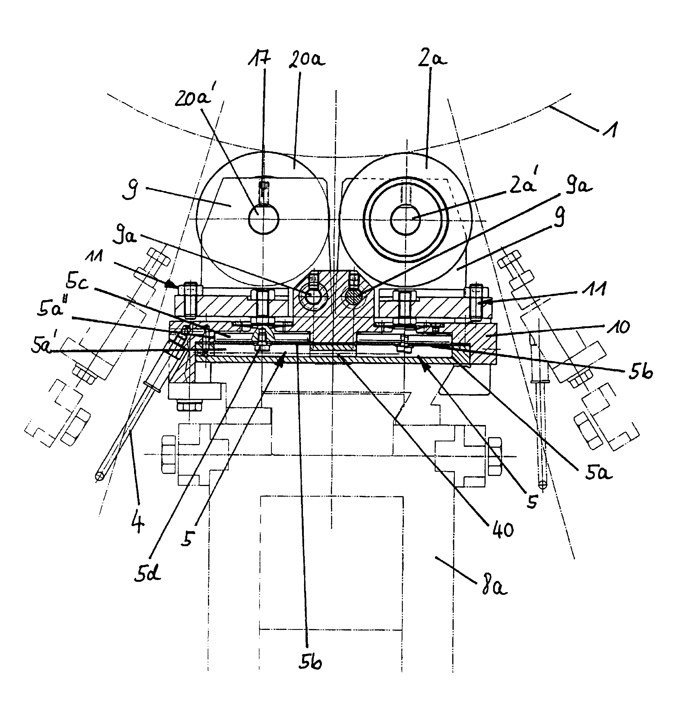
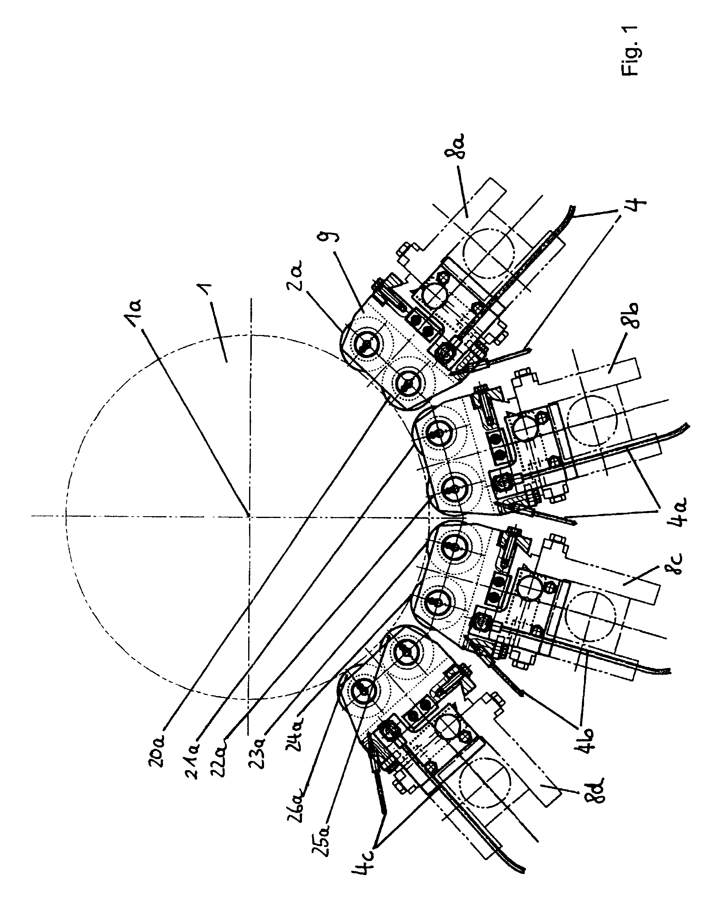
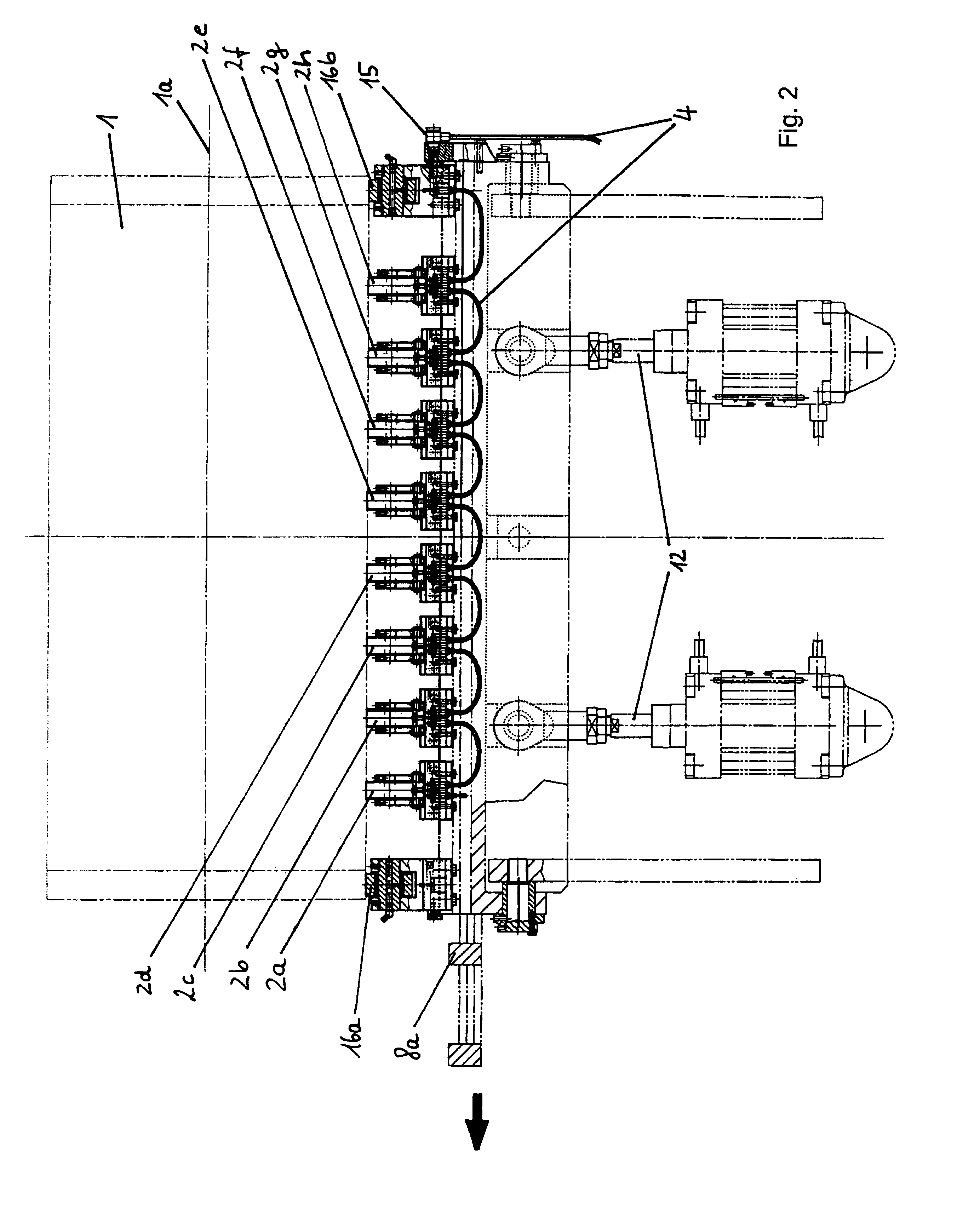
FIG. 1 shows an apparatus viewing in the direction of the longitudinal axis 1a of a heated support roller. It is possible to see from FIG. 1 four carriages 8a, 8b, 8c, 8d provided with pressure rollers 2a, 20a, 21a, 22a, 23a, 24a, 25a, 26a which form a roller cage and which press successively against the diameter of the support roller 1. In that case the pressure rollers 2a, 20a are arranged as a pair of pressure rollers on the first carriage 8a, the pressure rollers 21a, 22a are arranged as a pair of pressure rollers on the carriage 8b, the pressure rollers 23a, 24a are arranged as a pair of pressure rollers on the carriage 8c and the pressure rollers 25a, 26a are arranged as a pair of pressure rollers on the carriage 8d. In this case the pressure rollers are mounted in bearing arrangements 9 and are preferably formed from phenol resin pressing material or a similar material. A transfer film (not shown) and a web of material (not shown) are passed between the support roller 1 and t...


PUM

PropertyMeasurementUnit
travel distancesaaaaaaaaaa

Abstract

The invention concerns an apparatus for applying at least one surface portion of a transfer layer of a transfer film to a web of material, wherein the apparatus has at least one support roller and at least one pressure roller for pressing the web of material and the transfer firm against the at least one support roller, wherein the at least one pressure roller is pneumatically or hydraulically resiliently supported by means of at least one resilient arrangement in the form of a diaphragm spring and wherein the apparatus has at least one adjusting device for varying a spring rate of the at least one resilient arrangement and thus for varying a pressure contact force of the at least one pressure roller against the at least one support roller, and the use of such an apparatus.

Description

This application claims priority based on an International Application filed under the Patent Cooperation Treaty, PCT / DE2005 / 001039, filed on Jun. 10, 2005 and German Application No. 102004028524.1-16, filed on Jun. 11, 2004.BACKGROUND OF THE INVENTIONThe invention concerns an apparatus for applying at least one surface portion of a transfer layer of a transfer film to a web of material, wherein the apparatus has at least one support roller and at least one pressure roller for pressing the web of material and the transfer film against the at least one support roller, wherein the at least one pressure roller is resiliently supported by means of at least one resilient arrangement and wherein the apparatus has at least one adjusting device for varying a spring rate of the at least one resilient arrangement and thus for varying a pressure contact force of the at least one pressure roller against the at least one support roller. The invention further concerns the use of such an apparatus...

Claims


Application Information

Patent Timeline
Patent Type & Authority Patents(United States)
IPC IPC(8): B32B15/00B29C59/04B41F19/02B41F19/06
CPCB29C59/04B41F19/062Y10T156/1741Y10T156/1707Y10T156/1705Y10T156/1768Y10T156/171Y10T156/1712
Inventor MITSAM, REINWALDGWOSDZ-KAUPMANN, MICHAEL
Owner LEONHARD KURZ GMBH & CO KG
Learn More