Method, apparatus, and processes for producing potable water utilizing reverse osmosis at ocean depth in combination with shipboard moisture dehumidification

a technology of reverse osmosis and water supply, which is applied in the direction of vacuum distillation separation, multi-stage water/sewage treatment, domestic cooling apparatus, etc., can solve the problems of reducing the service life of the equipment etc. , to achieve the effect of related fouling, reducing the salt content, and reducing the risk of subsystem contamination

Inactive Publication Date: 2011-03-08
SALYER IVAL O
View PDF16 Cites 15 Cited by
  • Summary
  • Abstract
  • Description
  • Claims
  • Application Information

AI Technical Summary

Benefits of technology

In another option, the dehumidification subsystem may include a screen or related porous device through which a breeze, the wind or the like can carry the ambient air. Porous members located in the dehumidification subsystem allow the wicking of water (in the form of humidity in the ambient air) into a flowpath that drains into an appropriate trough or related sluice. Motors, winches or the like can be used to reposition the screen of the dehumidification subsystem so that it best aligns with the prevailing winds to take best advantage of the system's evaporative capabilities.
The system may further include a positioning mechanism that permits movement of at least the RO subsystem through various depths of the saline water supply. In this way, briny water being discharged from the RO subsystem is done so over a larger space, thereby reducing the likelihood of the briny water corrupting the water supply. In the present context, briny water is any such water that, when reintroduced into the supply from where it came, has a higher salt concentration that of the surrounding supply. For example, if the saline water supply is the sea, ocean or related body of water, the briny water would be that produced by the higher salinity RO subsystem discharge that is in turn placed back into the body of water. Thus, one purpose of continuous operation of the positioning mechanism associated with the RO subsystem during the lowering and raising of the RO unit is that the briny concentrate leaving the RO unit is dispersed over a very large area and therefore would not result in a significant difference in the salinity of the water through which is passes. An additional benefit is that this would prevent debris from accumulating on the surface of the membrane in the RO unit.
According to another aspect of the present invention, a shipboard water desalination apparatus is disclosed. The apparatus includes an RO subsystem with a saline water inlet, a purified water outlet and a membrane, a dehumidification subsystem and one or more storage tanks for the collection of purified water. As with the previous aspect, the membrane allows preferential passage of water relative to salt in a saline water supply such that the water that passes through the membrane has a reduced salt content (as well as that of other contaminants) relative to that of the supply. The RO subsystem is further configured as a passive device. In this way, pumps or related equipment that are needed in conventional RO system to attain the high inlet pressures necessary to force the water through the membranes are not required, as a hydrostatic pressure of the saline water supply present at the saline water inlet (due, for example, to at least the inlet of the apparatus being situated at a significant subsurface depth) is sufficient to pass water from the water supply through the membrane. Such passive pressure may be produced from the system operating at depth where water is at maximum density, such as where the water temperature is as close to 2° Celsius as possible. As with the previous aspect, continuous movement of the RO unit eliminates the accumulation of debris on the surface of the RO membrane that could otherwise cause problems in stationary RO units in use. Also as with the previous aspect, the dehumidification subsystem can at least partially condense water present in an ambient air supply. Preferably, the dehumidification subsystem avoids the use of salinated water as a cooling agent to reduce the risk of subsystem contamination and related fouling. In addition, using a cold water supply (such as the purified water from the RO subsystem) as the source of the temperature differential allows the dehumidification system to operate around the clock (i.e., experience a larger duty cycle) with greater efficiency because even at night (with a concomitantly cooler air temperature), the temperature differential would still be enough to allow subsystem operation, as the relatively cold temperature of the water accumulated in a container or containers used in the RO subsystem helps provide a temperature differential that makes the dehumidification unit of the dehumidification subsystem work.
Optionally, introducing the RO subsystem includes moving the RO subsystem during its operation as a way to reduce brine concentration in the adjacent water, in effect spreading out the briny water flowing out of the RO unit over a larger area. In one form, the condensing may include using one or more of the saline water supply and the purified water produced in the RO subsystem as a cooling liquid in the heat exchanger, which is preferably configured as a liquid-air heat exchanger. In a preferable option, the RO and dehumidification subsystems, as well as the storage tank, are mounted to or otherwise integrated onto a ship or related watercraft. As previously discussed, the storage tank may be made up of a series of separate tanks that can be interconnected through appropriate piping, valving and pumping apparatus. Placement of various storage tanks around the ship (such as around the ship periphery) can be used with such apparatus to advantageously promote ship balance by moving the stored potable water between the various tanks. In another option, the heat exchanger can be positioned, such as by rotating it relative to the ship or the supply of humid air to maximize heat exchange interaction.
In another option, the containers used to collect the purified RO water in the RO subsystem can be evacuated to a low pressure prior to being lowered into the ocean or related saline water supply. In one form, the pressure can be reduced to less than 1 psi to reduce or eliminate the back pressure in the container, thereby allowing it to fill more completely during operation without additional depressurizing being necessary during the cycle. In another option, cleaning steps may be undertaken to eliminate or otherwise reduce the likelihood of fouling from contaminant build-up, such as salt, organic matter or the like. In this way, the purified water can be additionally treated to provide disinfection to eliminate microorganisms. Likewise, additional filtration devices can be used to remove suspended particulates. After such treatment, the purified water collected in the storage container can then pumped out for subsequent use by the dehumidification system, storage in the shipboard storage tanks, or both.

Problems solved by technology

Because the availability of freshwater supplies is limited by size, cleanliness and lack of accessibility, there exists a need for creating potable water from other sources.
Stewardship measures such as conservation and reuse, while laudable, will not in and of themselves be sufficient to meet the increase in worldwide water demand.
Unfortunately, their high saline content precludes their use as a supply of potable water.
Active evaporation is expensive, requiring vast amounts of energy (typically in the form of a combustible heat supply).
For example, because RO facilities generate significant quantities of dissolved solids and related effluent, release of such byproducts could be harmful if reintroduced in localized, concentrated form into the water supply from which it was derived.
Such localized release of effluent would eventually cause the water being taken into the system to become concentrated enough that it can impact the performance of the RO system membranes.
Similarly for evaporative systems, local nuisance concerns may mean that there are significant costs associated with keeping the facility at a suitable distance from population centers.
In either situation, the solution tends to be cost-prohibitive.
Such systems, while operationally suitable, are expensive, require significant amounts of energy consumption, and take up precious shipboard space.

Method used


Image

  • Method, apparatus, and processes for producing potable water utilizing reverse osmosis at ocean depth in combination with shipboard moisture dehumidification
  • Method, apparatus, and processes for producing potable water utilizing reverse osmosis at ocean depth in combination with shipboard moisture dehumidification
  • Method, apparatus, and processes for producing potable water utilizing reverse osmosis at ocean depth in combination with shipboard moisture dehumidification

Examples


Embodiment Construction

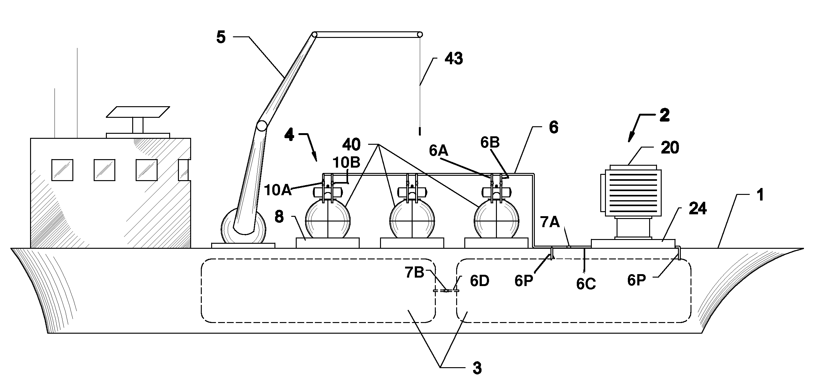
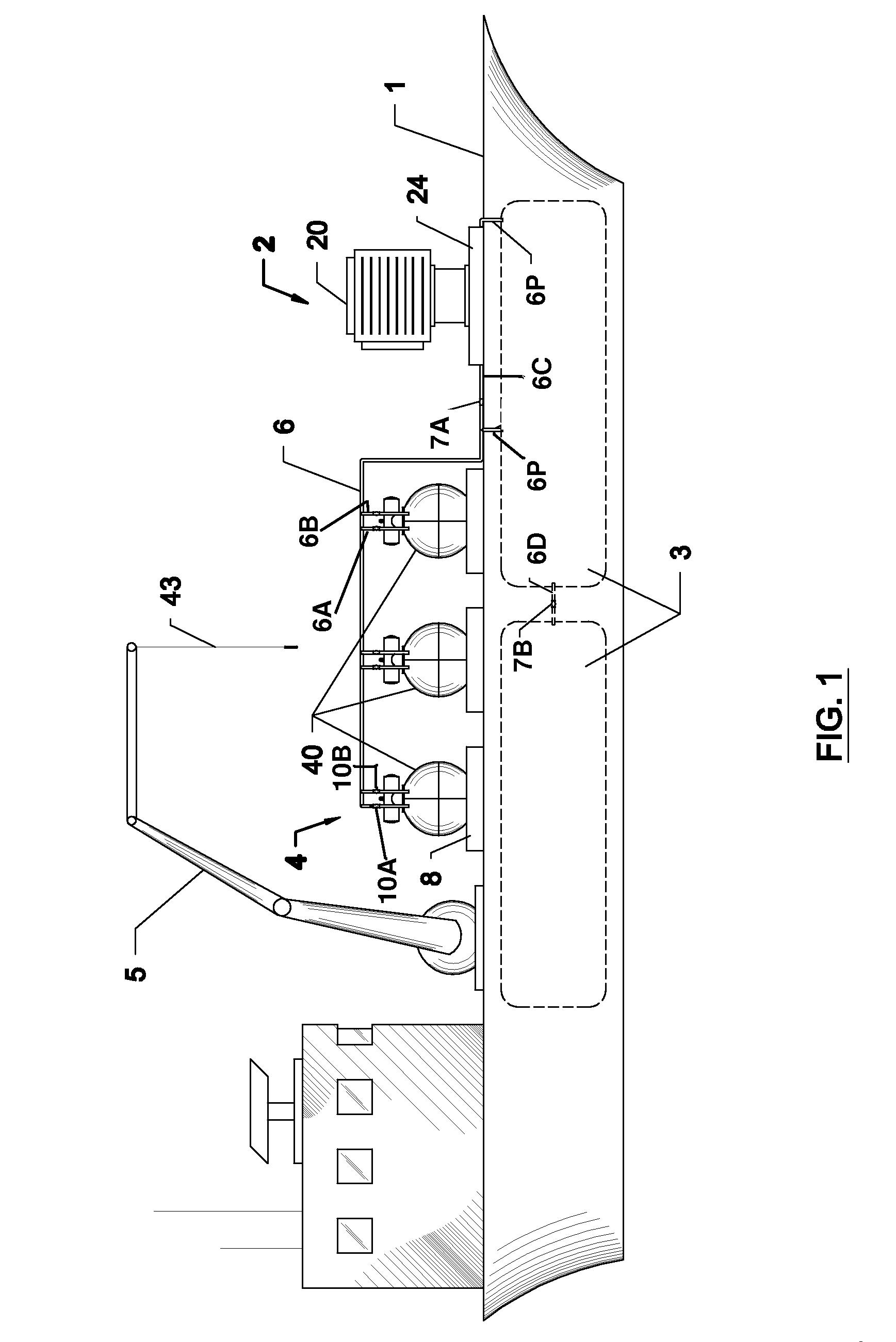
Referring initially to FIG. 1, a ship 1 (such as a tanker) outfitted with a potable water generation system according to an aspect of the present invention is shown. Ship 1 includes a dehumidification subsystem 2, one or more purified water storage tanks 3, RO subsystem 4, a crane or winch 5 and piping 6 that can convey the cold water from the RO subsystem 4 storage container to the dehumidification subsystem 2, and tanks 3. In a preferred form, the ship 1 is of a large-displacement variety. For example, the ship 1 may be a minimum 40,000 ton capacity, appropriately designed or modified as shown for the purpose of potable water production and storage. Such size must consider the ease with which ship 1 can navigate into and out of smaller ports and waterways, and it will be appreciated by those skilled in the art that different sizes commensurate with these restrictions are within the scope of the present invention.

The tanks 3 are preferably sterile, while portions of the piping 6 an...


PUM

PropertyMeasurementUnit
pressureaaaaaaaaaa
pressureaaaaaaaaaa
pressureaaaaaaaaaa

Abstract

Devices and methods for producing purified water. The device includes a reverse osmosis subsystem, a dehumidification subsystem and a purified water storage tank fluidly coupled to the subsystems such that purified water produced by each can be locally stored. A vehicular platform, such as a ship, can be used to locate the device adjacent a supply of saline water and humid air. A saline water inlet, membrane and purified water outlet cooperate in the reverse osmosis subsystem to allow preferential passage of water relative to salt in a saline water supply, while the dehumidification subsystem includes a heat exchanger that extracts moisture from the ambient humid air. Purified water produced by each of the subsystems can be used as a potable water source. When used in conjunction with a ship, part or all of the reverse osmosis subsystem can be submersed to a depth sufficient to generate a hydrostatic pressure that is in turn sufficient to passively operate the reverse osmosis membrane such that additional pressurizing equipment, such as a pump, is not needed. Furthermore, the temperature of the water purified by the reverse osmosis subsystem may be low enough to be used as a condensing agent for the ambient humid air passing through the dehumidification subsystem.

Description

BACKGROUND OF THE INVENTIONThe present invention relates generally to an apparatus and process for producing potable water using a combination of reverse osmosis (RO) and dehumidification, and more particularly to a combination of shipboard RO and dehumidification to extract and store potable water from a saltwater supply.A concomitant to an increase in global population is the need for potable water for human consumption, as well as for industrial, agricultural and other uses. Because the availability of freshwater supplies is limited by size, cleanliness and lack of accessibility, there exists a need for creating potable water from other sources. Stewardship measures such as conservation and reuse, while laudable, will not in and of themselves be sufficient to meet the increase in worldwide water demand.The world's seas and oceans are the most notable source of yet relatively untapped water. Unfortunately, their high saline content precludes their use as a supply of potable water....

Claims


Application Information

Patent Timeline
Patent Type & Authority Patents(United States)
IPC IPC(8): B01D61/00F25D25/00F25D17/06E02B15/00C02F3/12B01D3/10B01D63/00
CPCB01D5/0024B01D5/0057B01D5/0084B01D61/08B01D61/10C02F1/441C02F2103/08C02F2201/008Y02A20/131Y02A20/00Y02A20/124
Inventor SALYER, IVAL O.
Owner SALYER IVAL O
Why Eureka
Try Eureka