Reconfigurable electronic circuit

a technology of electronic circuits and reconfigurable components, applied in the direction of pulse techniques, instruments, computation using denominational number representation, etc., can solve the problems of continuous refreshing, limitations on the power consumption and form factor scale of the system, and what is lacking in the prior ar

Inactive Publication Date: 2011-03-08
THE UNITED STATES OF AMERICA AS REPRESETNED BY THE SEC OF THE AIR FORCE
View PDF1 Cites 39 Cited by
  • Summary
  • Abstract
  • Description
  • Claims
  • Application Information

AI Technical Summary

Benefits of technology

[0007]It is an object of the present invention to provide a method and apparatus that permits extremely low power co

Problems solved by technology

In addition, high charge leakage issues in the device require continuous refreshing of the processed information during standby and operation.
This continuous need for power creates limitations on the system's power consumption and form factor scale.
What is lacking in

Method used


Image

  • Reconfigurable electronic circuit
  • Reconfigurable electronic circuit
  • Reconfigurable electronic circuit

Examples


Embodiment Construction

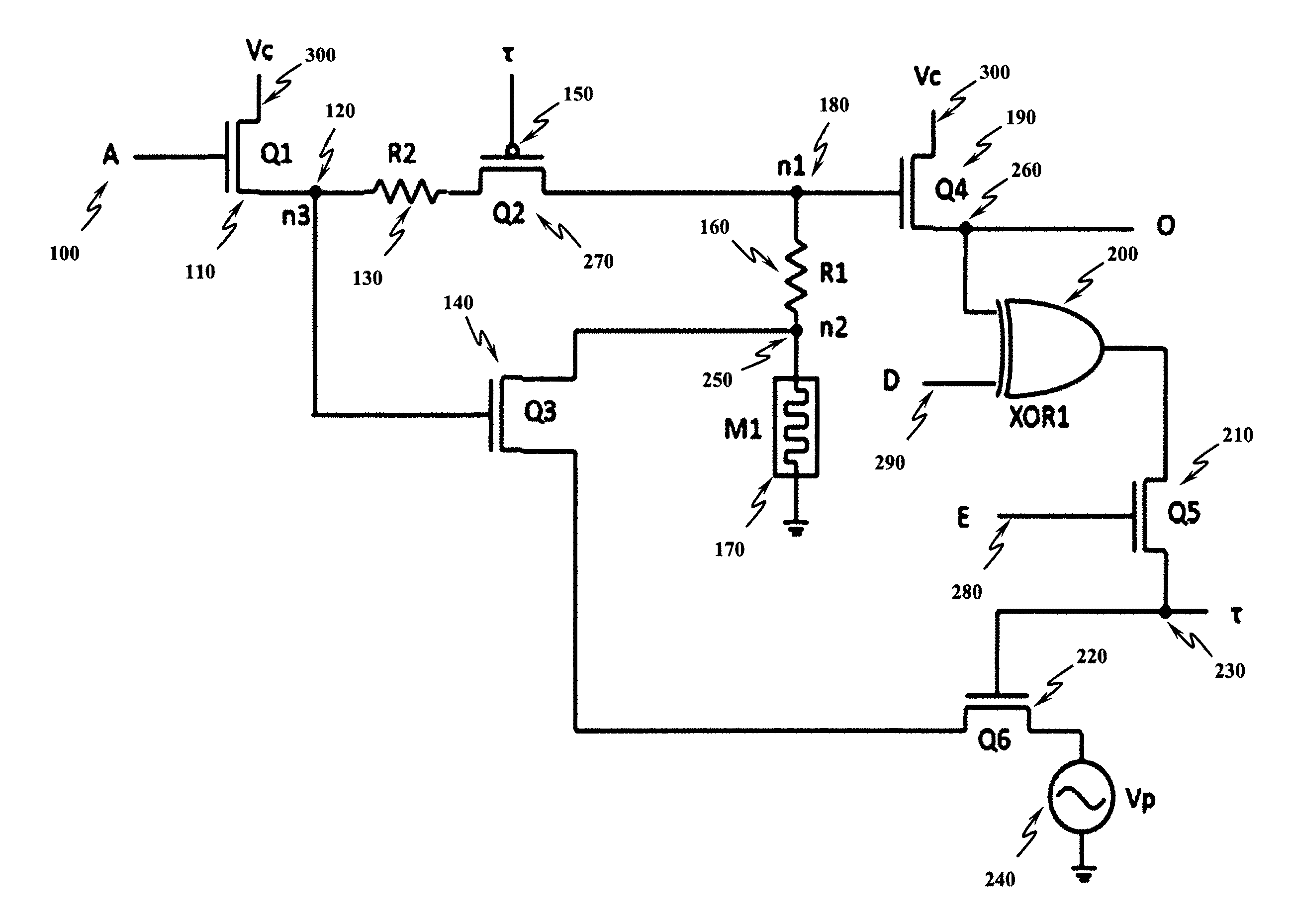
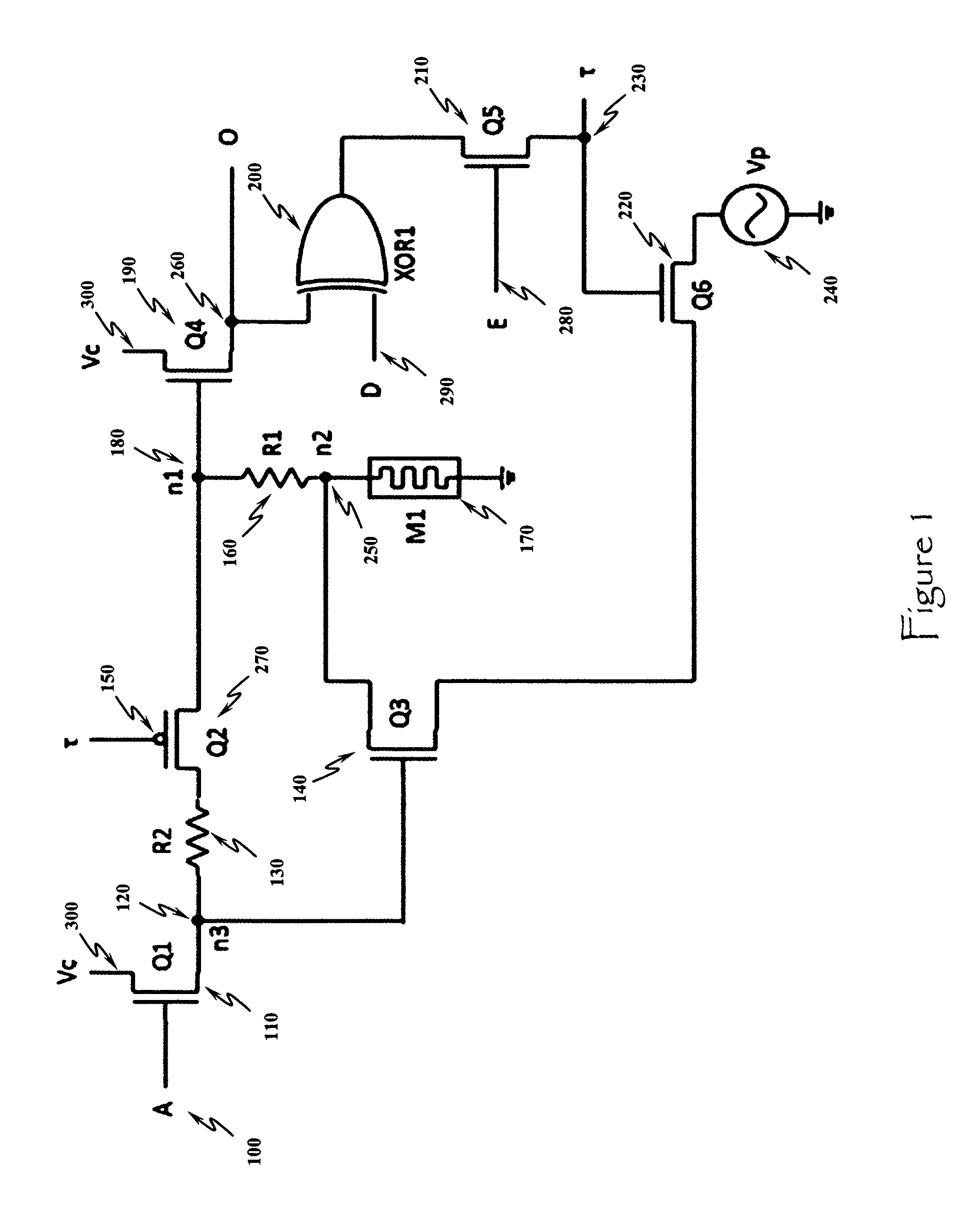
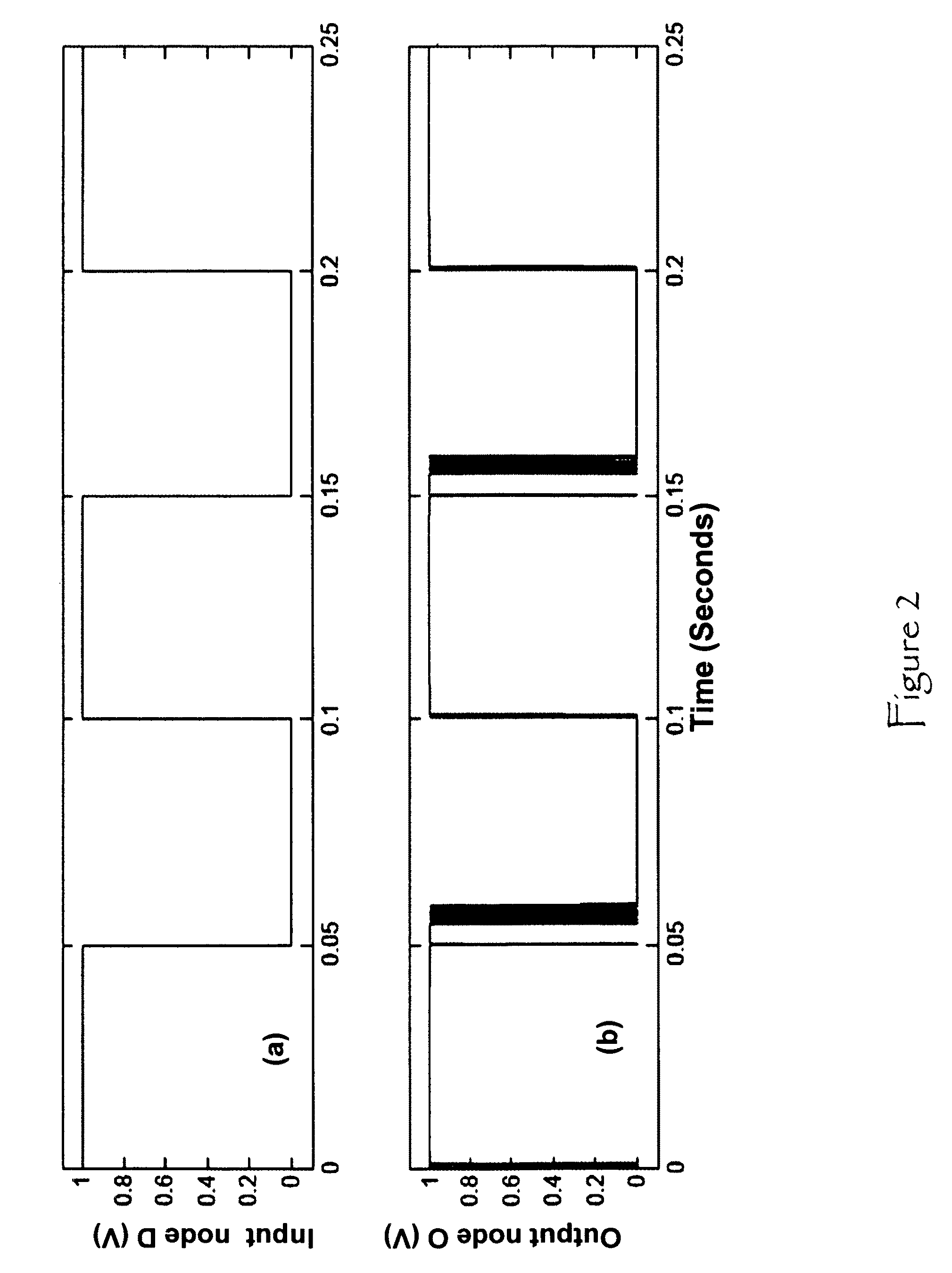
[0026]The present invention provides an apparatus and method for reprogrammable electronic circuit. The present invention employs a memristor-based approach within an innovative CMOS circuit biasing architecture to achieve autonomous electronic reconfigurability or reprogramming ability from a determined desired output and input signals. Simulation results performed on a hybrid CMOS and memristor device circuit demonstrate that a hardware realization of such electronic reconfigurable or reprogrammable system employing chalcogenide-based memristors and existing CMOS technologies is possible. The present invention represents the primitive building block for high density, small form-factor, and ultra-low power computing architectures.

[0027]The present invention leverages recent technological advances and discoveries namely the nonvolatile memory resistor device or “memristor” for short [1] and recent inventions in memristor modeling methodology [2], [6].

[0028]An important challenge in ...


PUM


Abstract

An apparatus and method provides the foundation for designing reconfigurable electronic computing systems. The invention relies on an ability to change the resistance state of a memristor device to achieve an optimal voltage at specific circuit nodes, whereby this dynamically and autonomously causes the circuit to reconfigure itself and produce a different output for the same input relative to the circuit's initial state. The circuit's state remains constant until the memristor's resistance is changed, at which point the circuit's function is “reprogrammed”.

Description

STATEMENT OF GOVERNMENT INTEREST[0001]The invention described herein may be manufactured and used by or for the Government for governmental purposes without the payment of any royalty thereon.BACKGROUND OF THE INVENTION[0002]This invention relates generally to the field of electronic circuit design. More specifically, this invention relates to electronic circuits which have a reprogrammable function.[0003]Current, conventional digital computing architectures rely solely on the field effect transistor (FET) which is a four terminal device (drain, gate, source, and body). However, during operation for storing or retrieving information the FET device needs to be powered continuously. In addition, high charge leakage issues in the device require continuous refreshing of the processed information during standby and operation. This continuous need for power creates limitations on the system's power consumption and form factor scale.[0004]One potential solution for computing architectures ...

Claims


Application Information

Patent Timeline
IPC IPC(8): H03K19/094G06F7/38
CPCG11C13/0011G11C13/0069
Inventor PINO, ROBINSON E.
Owner THE UNITED STATES OF AMERICA AS REPRESETNED BY THE SEC OF THE AIR FORCE
Why Eureka
Try Eureka