
Inspection fixture for the simultaneous admission of a disk-shaped test specimen with a search gas and a mechanical load as well as pertinent testing method

a technology of search gas and test specimen, applied in the direction of fluid tightness measurement, material strength using steady bending force, instruments, etc., can solve the problems of material change in mechanical properties or strength, method failure, and the greatest variety of materials are frequently subjected in practice to high mechanical loads, so as to reduce the gap width and the flow rate of the test gas.

Inactive Publication Date: 2011-03-15
BAM BUNDESANSTALT FUER MATERIALFORSCHUNG UND
View PDF6 Cites 2 Cited by
  • Summary
  • Abstract
  • Description
  • Claims
  • Application Information

AI Technical Summary

Benefits of technology

Enables a more accurate assessment of material failure risk by simulating real-world conditions cost-effectively, allowing for the evaluation of material performance under combined mechanical and corrosive stress, thereby overcoming limitations of previous test methods.

Problems solved by technology

Components made of the greatest variety of materials are frequently subject in practice to high mechanical loads in the presence of corrosively flowing gases under pressure.
This method fails when the material changes its mechanical properties or loses strength more intensely than provided for in the risk factor.
The method can fail in particular if there is positive feedback between the mechanical load and the corrosion, i.e., the rate of corrosion increases under load.
A consequence of the limitations of the known test methods is that for safety reasons the full potential of the materials used is not incorporated in the calculation of the risk of failure.
Known test devices and associated test methods have other disadvantages depending on the design and application, such as:For the most part, an additional total pressure can be applied from inside only in hollow test specimens.
Manufacturing these types of test specimens is very cost-intensive.Often the selection of the corrosive media is severely limited by the procedural steps for mechanical load initiation and the specimen holder.Special test specimens, which are very expensive to manufacture, are used in standardized tensile tests.Often the test specimens are heated.

Method used


Image

  • Inspection fixture for the simultaneous admission of a disk-shaped test specimen with a search gas and a mechanical load as well as pertinent testing method

Examples


Embodiment Construction

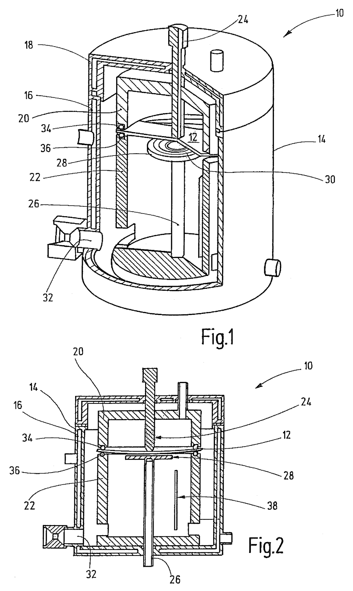
[0047]FIGS. 1 and 2 show different sectional representations of a test device 10 for simultaneously exposing a disk-shaped test specimen 12 to a test gas (as a rule a flowing and pressurized corrosive gas) and mechanical load.

[0048]As shown here, the test specimen 12 is available as a circular disk made of the to-be-tested material, for example a metallic material. Producing these types of test specimens 12 for the test device 10 can be realized in a simple manner with the aid of known processing methods so that it is possible at this point to dispense with a more detailed explanation.

[0049]The test device 10 is designed as a pressure-resistant test container 14, configured in this case of two elements with a vessel 16 and an associated cover 18. The vessel 16 as well as the cover 18 contains a double jacket that can be permeated by a coolant. The coolant can be water for example, which circulates via a thermostat (not shown in this case).

[0050]Located in the interior of the test co...


PUM

PropertyMeasurementUnit
temperatureaaaaaaaaaa
pressureaaaaaaaaaa

Abstract

The invention relates to a test device for simultaneously exposing a disk-shaped test specimen to a flowing and pressurized test gas and mechanical load as well as an associated test method. The test device is comprised of the following components: a specimen seat, which is designed in such a way that an edge area of the test specimen rests on the specimen seat and an inner area of the test specimen is accessible from its upper side and lower side; a ram arranged above the specimen seat, with which a presettable mechanical load can be exerted on the upper side of the test specimen; and a gas feed plate arranged beneath the specimen seat, with which the test gas can be conveyed to the lower side of the test specimen.

Description

TECHNICAL FIELD[0001]The invention relates to a test device for simultaneously exposing a disk-shaped test specimen to a flowing and pressurized test gas and mechanical load as well as an associated test method.BACKGROUND[0002]Components made of the greatest variety of materials are frequently subject in practice to high mechanical loads in the presence of corrosively flowing gases under pressure. Examples of these types of components include gas turbine blades, compressors, pipelines and CO2 injectors for oil and gas producing facilities for developing oil or gas fields. The first time new or even known materials are used in these types of components requires an assessment of the risk of failure. Previous design methods utilize characteristic values, which are derived from pure mechanical tests and pure corrosive tests. For the most part, the results are combined in such a way that the material loss or the weakening from gas erosion and gas corrosion is computed over time and a mec...

Claims


Application Information

Patent Timeline
Patent Type & Authority Patents(United States)
IPC IPC(8): G01N3/00G01M3/04G01M99/00
CPCG01N3/02G01N17/002G01N3/20G01N2203/0023G01N2203/0037G01N2203/0042G01N2203/0044G01N2203/0252G01N2203/0282G01N2203/024G01N2203/0242
Inventor KRANZMANN, AXELHUNERT, DANIELA
Owner BAM BUNDESANSTALT FUER MATERIALFORSCHUNG UND
Learn More