Pitch actuator for wind turbine generator, and wind turbine generator

a technology of pitch actuator and wind turbine, which is applied in the direction of rotors, vessel construction, marine propulsion, etc., can solve the problems of high load, less reliability of pitch actuator, and more susceptible deformation of the joint structure between the trunnion structure and the hydraulic cylinder, so as to prevent the loss of reliability of the pitch actuator

Inactive Publication Date: 2011-03-15
MITSUBISHI HEAVY IND LTD
View PDF8 Cites 8 Cited by
  • Summary
  • Abstract
  • Description
  • Claims
  • Application Information

AI Technical Summary

Benefits of technology

[0010]In addition, a force acting on a larger wind turbine rotor blade can deform the root of the wind turbine rotor blade, or the rotor head itself, thus imposing a higher load acting about the axis perpendicular to the rotation axis of the trunnion structure.
[0013]An object of the present invention, which has been made to solve the above problems, is to provide a pitch actuator for a wind turbine generator and a wind turbine generator that can be prevented from losing their reliability.
[0018]Accordingly, the cylinder bearing can absorb a force acting in such a direction as to bend the cylinder and the rod to prevent accelerated wear of, for example, a seal around the cylinder. In addition, the assembly tolerance required for assembly of the pitch actuator of the present invention can be alleviated.
[0023]By doing so, because a spherical bearing is used as the rod bearing, the force acting in such a direction as to bend the cylinder and the rod is also absorbed between an end of the rod and the wind turbine rotor blade by the rod bearing. This more reliably prevents accelerated wear of, for example, the seal around the cylinder and more significantly alleviates the assembly tolerance required for assembly of the pitch actuator of the present invention.
[0025]In the second aspect of the present invention, because the pitch actuators according to the first aspect of the present invention are used, the pitch actuators are prevented from losing their reliability, so that the wind turbine generator can be prevented from losing its reliability.
[0026]In the pitch actuator for a wind turbine generator according to the first aspect of the present invention and the wind turbine generator according to the second aspect, a force acting on the cylinder and the rod due to strain occurring at the joint between the rotor head and the wind turbine rotor blade is absorbed as the cylinder and the rod rotate about the second rotation axis. On the other hand, when the pitch angle is changed, the cylinder and the rod rotate about the first rotation axis as the wind turbine rotor blade rotates. That is, the cylinder bearing absorbs a force acting in such a direction as to bend the cylinder and the rod, so that the benefit of preventing the pitch actuator from losing its reliability is provided.

Problems solved by technology

In this pitch actuation mechanism, however, the joint structure between the trunnion structure and the hydraulic cylinder is more susceptible to deformation as the stroke of the hydraulic cylinder and the rod is extended for some reason, such as increasing the size of wind turbine generator, and can therefore experience a higher load acting about the axis perpendicular to the rotation axis of the trunnion structure.
Such a high load wears a seal around the hydraulic cylinder and imposes a higher structural load on the trunnion structure, thus causing a problem in that the pitch-actuating mechanism can lose its reliability in the long term.
In addition to the above problem, care must be taken in assembly of the pitch actuation mechanism to prevent, for example, wear of the seal around the hydraulic cylinder because of strict requirements for parallelism with the rotation surface of the wind turbine rotor blade.

Method used


Image

  • Pitch actuator for wind turbine generator, and wind turbine generator
  • Pitch actuator for wind turbine generator, and wind turbine generator
  • Pitch actuator for wind turbine generator, and wind turbine generator

Examples


Embodiment Construction

[0049]A wind turbine generator according to an embodiment of the present invention will now be described with reference to FIGS. 1 to 6.

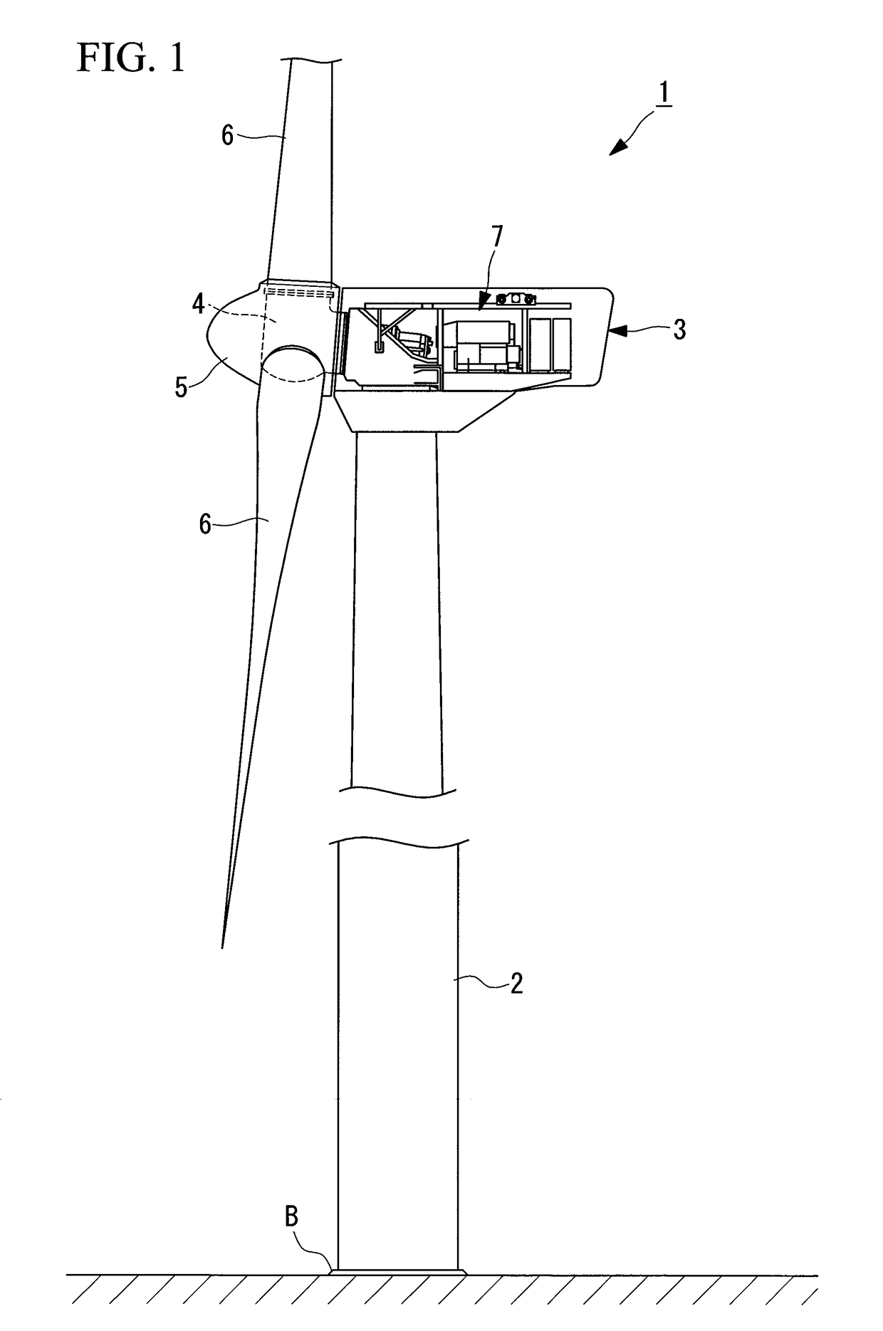
[0050]FIG. 1 is a diagram illustrating the structure of the wind turbine generator according to this embodiment.

[0051]As shown in FIG. 1, a wind turbine generator 1 generates electricity by wind power. The wind turbine generator 1 includes a tower 2 disposed upright on a foundation B, a nacelle 3 disposed at the top end of the tower 2, a rotor head 4 disposed on the nacelle 3 so as to be rotatable about a substantially horizontal axis, a head capsule 5 covering the rotor head 4, a plurality of wind turbine rotor blades 6 attached to the rotor head 4 radially around the rotation axis thereof, and electricity-generating equipment 7 that generates electricity as the rotor head 4 rotates.

[0052]Although an example in which three wind turbine rotor blades 6 are disposed is described in this embodiment, the number of wind turbine rotor blades 6 is not limi...


PUM


Abstract

Provided are a pitch actuator for a wind turbine generator and a wind turbine generator that can be prevented from losing their reliability. Provided are a cylinder (12) and a rod (13) that rotate a wind turbine rotor blade about an axis thereof relative to a rotor head to change a pitch angle; a cylinder bearing (14, 15) supporting the cylinder (12) so as to be rotatable relative to the rotor head about a first rotation axis (L1) extending substantially parallel to the axis of the wind turbine rotor blade and about a second rotation axis (L2) extending in a direction crossing both the first rotation axis (L1) and the axis of the cylinder (12) and the rod (13); and a rod bearing (16) rotatably supporting an end of the rod (13) on an end surface of the wind turbine rotor blade.

Description

CROSS-REFERENCE TO RELATED APPLICATIONS[0001]The present Application is based on International Application No. PCT / JP2008 / 057911, filed on Apr. 24, 2008, which in turn corresponds to Japanese Application No. 2007-139434 filed on May 25, 2007, and priority is hereby claimed under 35 USC §119 based on these applications. Each of these applications are hereby incorporated by reference in their entirety into the present application.TECHNICAL FIELD[0002]The present invention relates to pitch actuators for wind turbine generator and also to wind turbine generator.BACKGROUND ART[0003]Known wind turbines used for wind turbine generator include those having wind turbine rotor blades with a fixed pitch angle and those having wind turbine rotor blades with a variable pitch angle.[0004]An example of a known mechanism for changing the pitch angle of the above wind turbine rotor blades is a mechanism by which linear movement of a rod in a hydraulic cylinder is converted into rotation of a wind tu...

Claims


Application Information

Patent Timeline
Patent Type & Authority Patents(United States)
IPC IPC(8): F03D9/00
CPCF03D7/0224F03D11/0008F05B2260/74F05B2270/604Y02E10/721Y02E10/723F05B2270/1095F05B2240/50F05B2250/42F05B2260/507F05B2260/76Y02E10/722F03D80/70Y02E10/72
Inventor NUMAJIRI, TOMOHIROKAWAI, MASAHIROSEKI, SEITA
Owner MITSUBISHI HEAVY IND LTD
Why Eureka
Try Eureka