Clothes dryer

a dryer and cloth technology, applied in the field of cloth dryers, can solve the problems of large energy consumption, shortened overall drying time, and large probability of damage depending on the material of laundry in the drying procedure, and achieve the effect of improving energy efficiency and little possibility of causing damage to laundry

Active Publication Date: 2011-03-22
LG ELECTRONICS INC
View PDF406 Cites 66 Cited by
  • Summary
  • Abstract
  • Description
  • Claims
  • Application Information

AI Technical Summary

Benefits of technology

[0008]Therefore, an object of the present invention is to provide a clothes dryer which improves energy efficiency and has little possibility of causing a damage to laundry due to a high temperature air in a drying procedure.
[0009]Another object of the present invention is to provide a clothes dryer which can introduce air to a drying drum with moisture removed enough from the introduced air.
[0010]Still another object of the present invention is to provide a clothes dryer which is compact with improved space utilization.

Problems solved by technology

Although such a conventional clothes dryer that delivers heat to an introduced air by using a heater has a merit that the overall drying time is shortened by the heater's rapid heating of air and it can be manufactured to have a large capacity, it has a drawback that the energy consumption is large because an introduced air is heated by the heater.
Especially, there is a great probability that damages may occur depending on the material of laundry in the drying procedure since the laundry is dried with air of high temperature of 100° C. or higher.
Meanwhile, the condensation type clothes dryer has a merit that it can be manufactured in a built-in type since it requires no air exhaust duct for discharging air out of the clothes dryer, while it has a drawback that it requires a long drying time and is difficult to be manufactured to have a large capacity although its energy efficiency is higher than the exhaust type.
Meanwhile, in areas with a high humidity, for example, near seashores or areas with a long rain season, there is a problem in that the drying efficiency is relatively lower when the clothes dryer is used.
This is because a large amount of moisture is contained in the air used to dry laundry.
It requires a lot of time to dry laundry since the air containing a large amount of moisture is introduced into the drying drum with the moisture not being removed enough even if the air is increased in temperature by the heater, resultantly increasing the energy consumption required to complete the drying.

Method used


Image

  • Clothes dryer
  • Clothes dryer
  • Clothes dryer

Examples


Embodiment Construction

[0030]Hereinafter, preferred embodiments of the present invention will be described in more detail with reference to the accompanying drawings.

[0031]While the invention has been described in connection with preferred embodiments, it is not intended to limit the scope of the invention to the particular form set forth, but on the contrary, it is intended to cover such alternatives, modifications, and equivalents as may be included within the spirit and scope of the invention as defined by the appended claims.

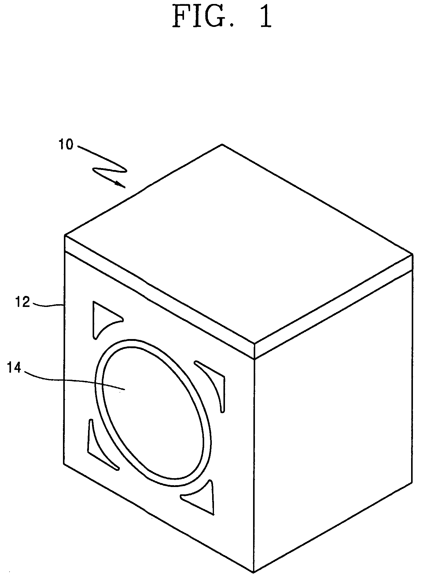
[0032]First, referring to FIG. 1, one example of a clothes dryer 10 according to the present invention is illustrated. A cabinet 12 provided with an entrance 14 in the front face is hollow inside, with a drying container rotationally mounted therein.

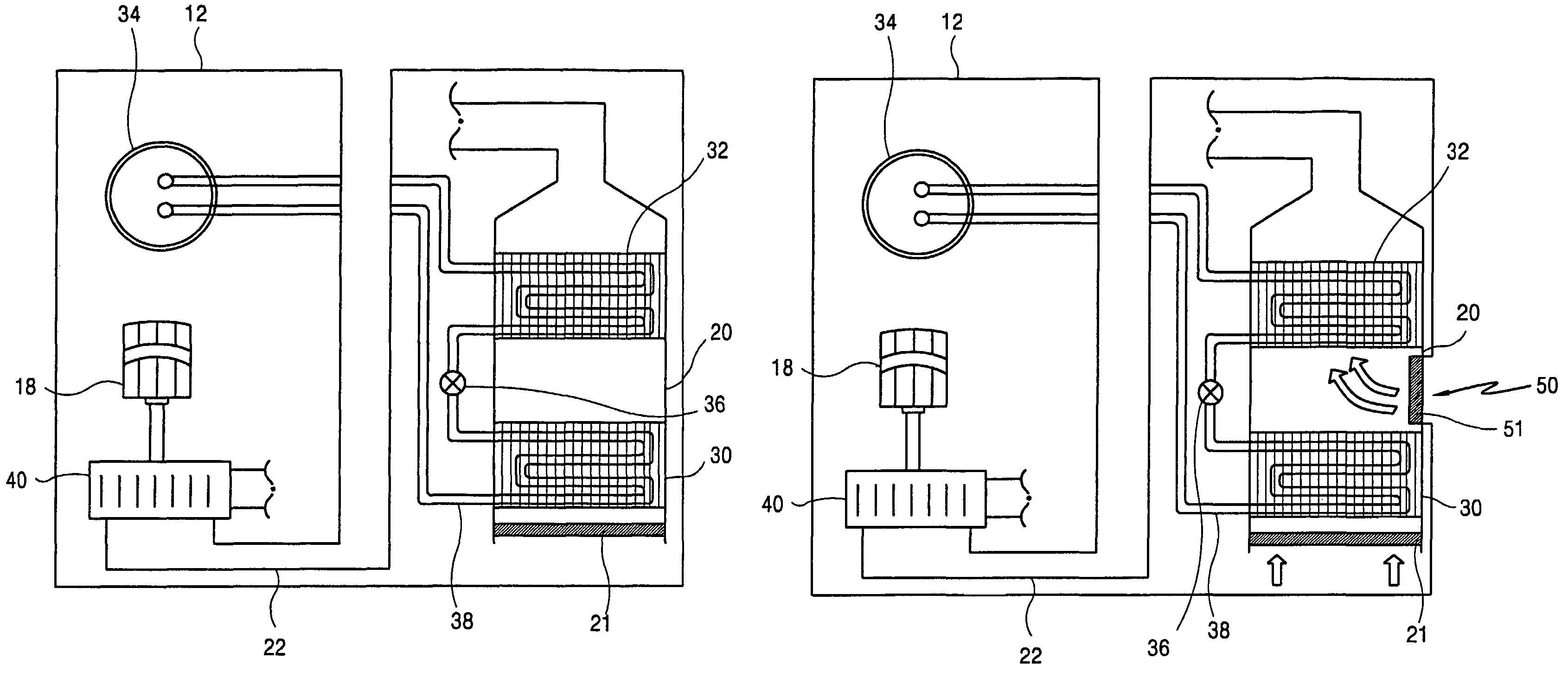
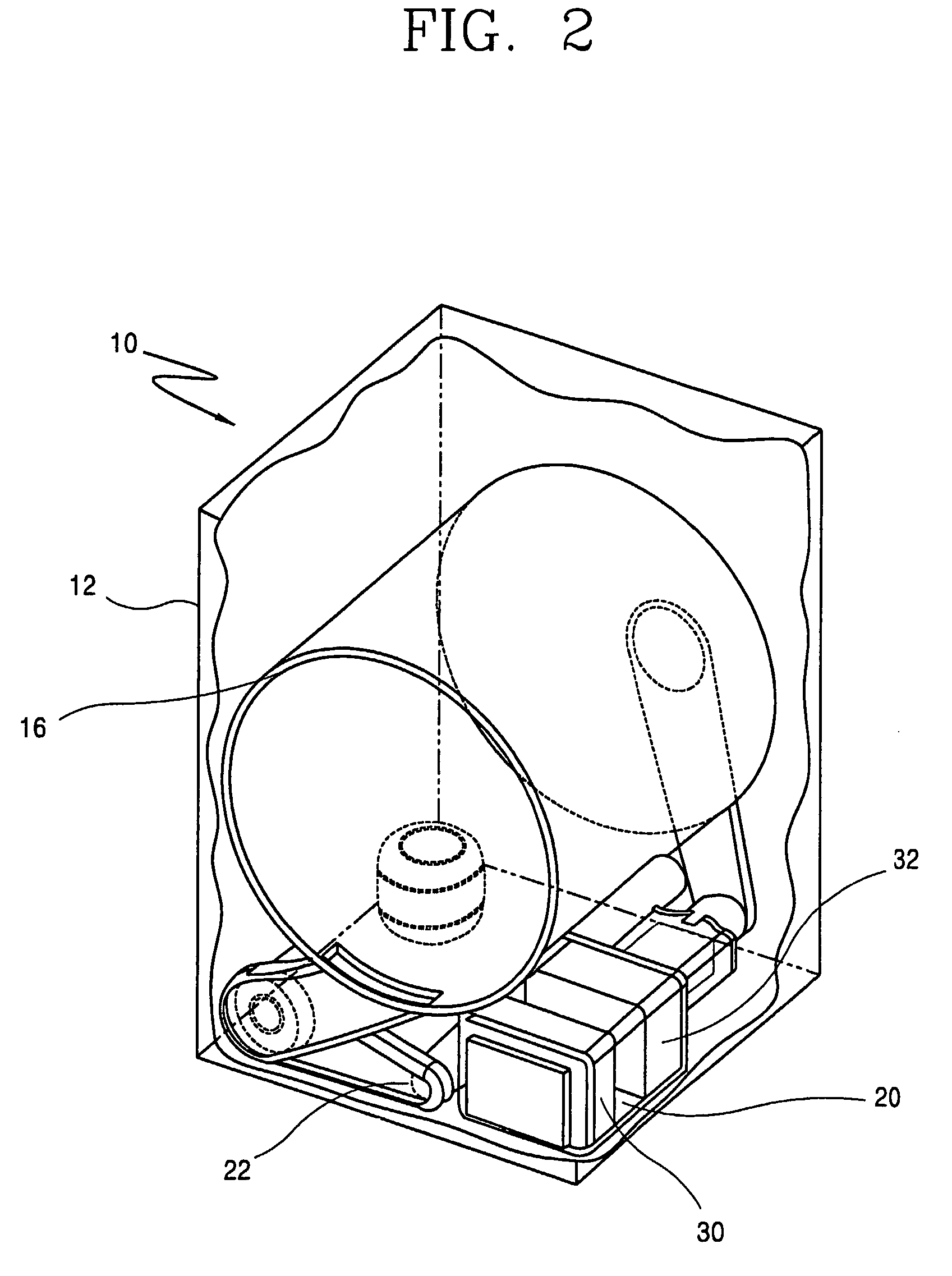
[0033]FIGS. 2 and 3 illustrates an inner structure of the clothes dryer in more detail.

[0034]The drying container 16 is a cylindrical-shaped structure, and disposed so as to rotate around an axis substantially parallel to the bottom of...


PUM

PropertyMeasurementUnit
temperatureaaaaaaaaaa

Abstract

A clothes dryer is provided. In the dryer, air flowing into a drying container is provided with heat from heat pump. The clothes dryer comprises a cabinet, a drying container rotationally mounted in the cabinet, a motor providing the container with rotational force, a first air path connected to a side of the container, a second air path connected to another side of the container and to the outside of the cabinet, and a first heat exchanging member and a second heat exchanging member in the first air path. A damper may be additionally included in the second air path.

Description

TECHNICAL FIELD[0001]The present invention relates to a clothes dryer, and more particularly, to a clothes dryer of exhaust type including a vapor compression cycle system. The clothes dryer improves drying efficiency by drying laundry by supplying heat to an introduced air from a heat exchange cycle system.BACKGROUND ART[0002]Clothes dryers are mainly used to dry clothes by removing moisture from clothes that have just been washed.[0003]The clothes dryers can be classified into an exhaust type and a condensation type according to a processing method of moist air generated while drying laundry. The former type employs a method of exhausting moist air from a dryer, while the latter employs a method of removing moisture by condensing moist air exhausted from a dryer and circulating the moisture-removed air again in the dryer.[0004]Typically, in the exhaust type dryer, an air intake duct and an air exhaust duct are connected to a rotatable drum disposed inside a cabinet, the air intake...

Claims


Application Information

Patent Timeline
Patent Type & Authority Patents(United States)
IPC IPC(8): F26B19/00
CPCD06F58/206D06F58/02D06F34/24D06F2103/32D06F2103/34D06F2105/32
Inventor AHN, SEUNG-PHYOBAEK, SEUNG-MYUNMOON, JUNG-WOOKKIM, DAE-WOONGRYOO, BYEONG-JO
Owner LG ELECTRONICS INC
Why Eureka
Try Eureka