
Virtual temperature measuring point

a temperature measurement and virtual technology, applied in the direction of instruments, furniture, material heat development, etc., can solve the problems of premature material wear, material stress, cracks, etc., and achieve the effect of accurate determination of the average integral wall temperature/axial

Inactive Publication Date: 2011-03-22
SIEMENS AG
View PDF7 Cites 3 Cited by
  • Summary
  • Abstract
  • Description
  • Claims
  • Application Information

AI Technical Summary

Benefits of technology

"The invention provides a method for accurately determining the average temperature of a thick-walled component during heating-up or cooling-down processes without the need for cost-intensive and error-prone measuring points. The method uses a multilayer model based on the average temperature of each layer, which is determined by a transient balancing of heat flows in individual layers. The method is advantageously stable and robust, and can be used in various industrial applications."

Problems solved by technology

During heating-up and cooling-down processes, as occur in component walls, for example in a steam turbine, a valve housing or a steam line, in particular when changing the operating mode, temperature gradients are produced in thick walls of these components and may lead to considerable material stresses.
These material stresses may lead to premature material wear to the extent that cracks form.
However, this method is comparatively cost-intensive and error-prone.
However, systems previously realized on this basis in the instrumentation and control of industrial plants, such as for example tubes of steam power plants, have a tendency to undergo oscillations, dependent on the period of the temperature changes of the working medium, which limit reliable assessment of the temperature values obtained in such a way.

Method used


Image

  • Virtual temperature measuring point
  • Virtual temperature measuring point
  • Virtual temperature measuring point

Examples


Embodiment Construction

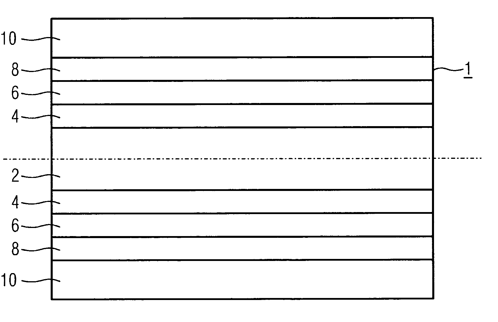
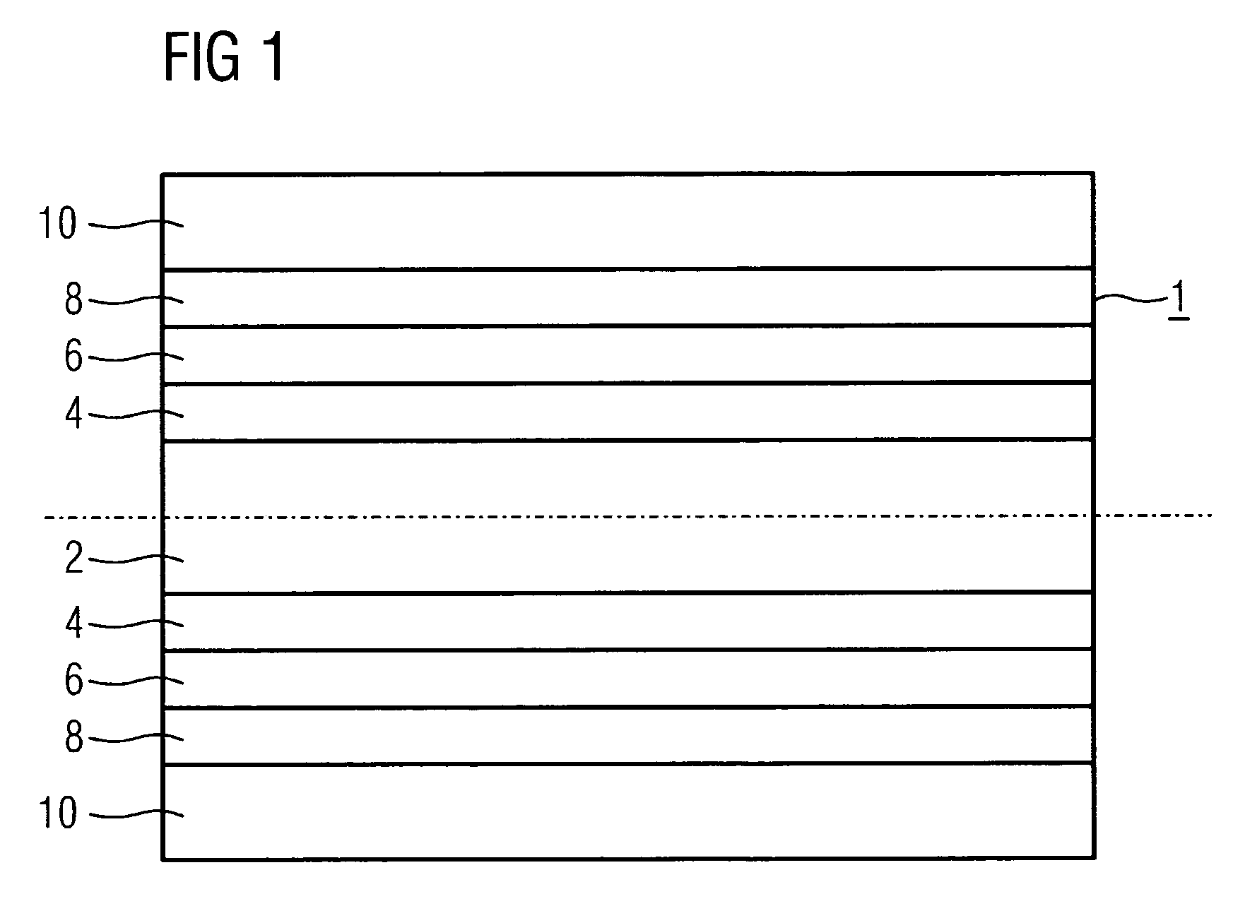
[0031]FIG. 1 shows a tube portion 1 in section as an example of a thick wall. The interior space 2 of the steam tube is flowed through by the working medium (steam), and from here the heat flow is transferred into the first layer 4. This is followed by the second layer 6 and the third layer 8. The tube portion 1 is enclosed by the insulation 10.

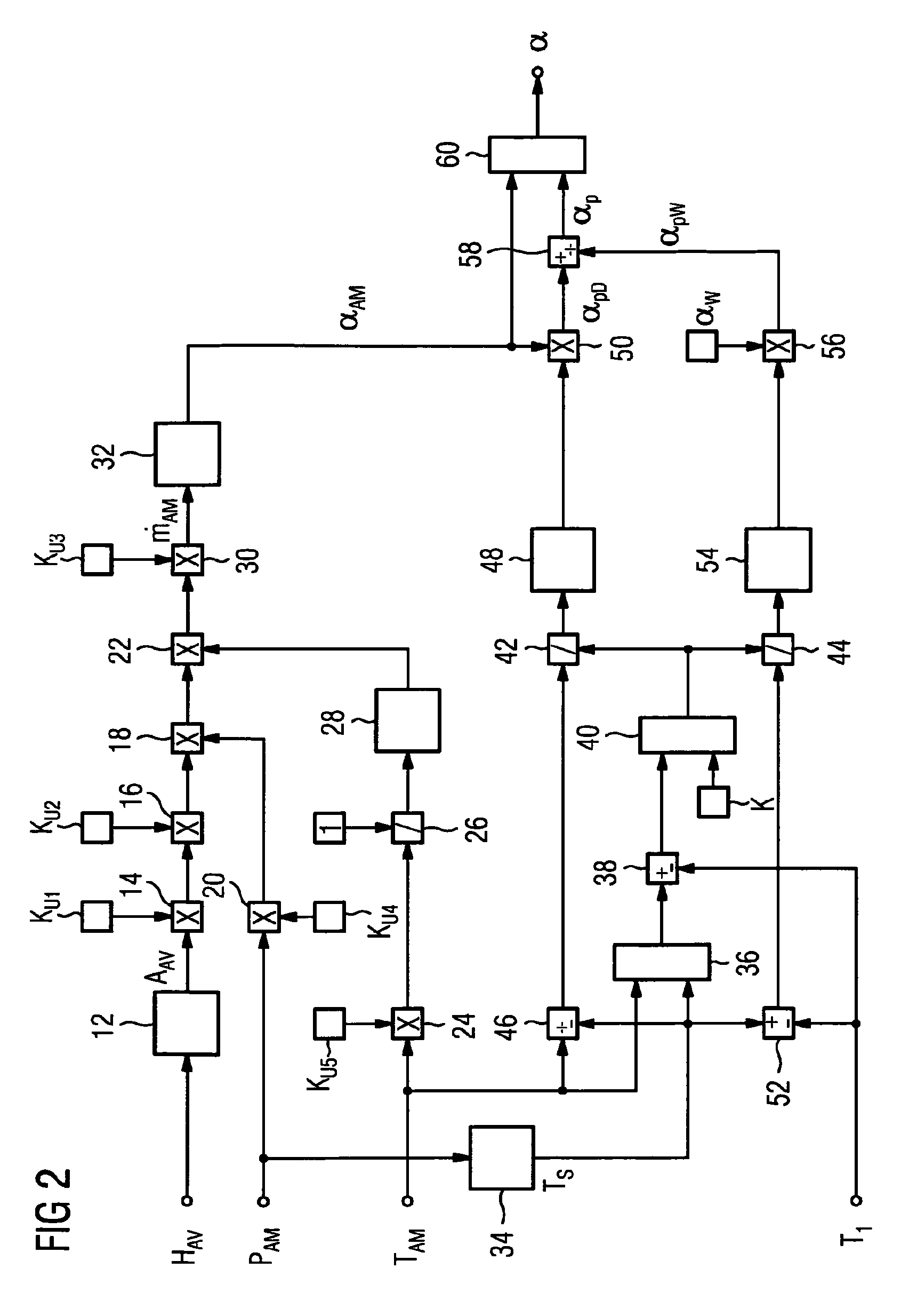
[0032]According to FIG. 2, the measured value of the steam throughput {dot over (m)}AM is fed as the input signal to the function generator 32, which calculates from this the heat transfer coefficient αAM as a function of the working medium {dot over (m)}AM for the case of steam, αAM=f({dot over (m)}AM). This function is given by a number of interpolation points, intermediate values being formed by suitable interpolation methods.

[0033]In order also to allow for the case of partial condensation, the pressure of the working medium pAM is also passed to the input of a function generator 34, which replicates the saturation function Ts=f(pAM), and...


PUM

PropertyMeasurementUnit
temperatureaaaaaaaaaa
mass flowaaaaaaaaaa
pressureaaaaaaaaaa

Abstract

The invention relates to a method for determining a temperature profile and the integral mean temperature and / or axis temperature in a thick wall or shaft. In order to determine a mean integral wall temperature during heating or cooling processes in a multilayer model, the mean integral wall temperature is calculated from the mean temperature of each layer. A multilayer model is used for determining the mean integral wall temperature during heating or cooling processes and draws upon the mean temperature of each layer.

Description

CROSS REFERENCE TO RELATED APPLICATIONS[0001]This application is the U.S. National Stage of International Application No. PCT / EP2006 / 066704, filed Sep. 25, 2006 and claims the benefit thereof. The International Application claims the benefits of European application No. 05022820.4 filed Oct. 19, 2005, both applications are incorporated by reference herein in their entirety.FIELD OF INVENTION[0002]The invention relates to a method for determining the temperature profile and the average integral temperature and / or axial temperature in walls or shafts of thick-walled components, such as for example of steam collectors, steam lines, valve housings, turbine housings or shafts or the like.BACKGROUND OF THE INVENTION[0003]During heating-up and cooling-down processes, as occur in component walls, for example in a steam turbine, a valve housing or a steam line, in particular when changing the operating mode, temperature gradients are produced in thick walls of these components and may lead t...

Claims


Application Information

Patent Timeline
Patent Type & Authority Patents(United States)
IPC IPC(8): G01K3/00G01N25/00
CPCF27D21/0014G01K17/20G01K7/42G01K19/00
Inventor ZAVISKA, OLDRICH
Owner SIEMENS AG
Learn More