Bidirectional drill string telemetry for measuring and drilling control

a telemetry and drill string technology, applied in the direction of instruments, survey, borehole/well accessories, etc., can solve the problems of insufficient rate, low data rate, and well known limitations of mud pulse telemetry, so as to improve the operation and decision-making, improve the effect of measurement and control

Active Publication Date: 2011-03-29
SCHLUMBERGER TECH CORP
View PDF39 Cites 81 Cited by
  • Summary
  • Abstract
  • Description
  • Claims
  • Application Information

AI Technical Summary

Benefits of technology

[0010]The present invention has features which, inter alia, take full advantage of recent advances in drill string telemetry. Substantially real time bidirectional communication is used to advantage, in embodiments hereof, to improve measurement and control, during the drilling (and pausing and tripping) processes, to achieve improved operation and decision making.

Problems solved by technology

However, mud pulse telemetry has well known limitations, including relatively slow communication, low data rates, and marginal reliability.
In many cases, this rate is insufficient to send all the data that is gathered by an LWD tool string, or is limiting on the configuration of a desired tool string.
Also, mud pulse technology does not work well in extended reach boreholes.
Signaling from uphole to downhole, by regulating mud pump flow, in order to control processes such as directional drilling and tool functions, is also slow, and has a very low information rate.
Also, under certain circumstances, for example underbalanced drilling employing gases or foamed drilling fluid, current mud pulse telemetry cannot function.
Data rates are estimated to be about an order of magnitude higher than mud pulse telemetry, but still limiting, and noise is a problem.
Acoustic telemetry has not yet become commercially available.
This technique is considered to have limited range, depends on characteristics, especially resistivity, of the formations surrounding the borehole, and also has limited data rates.

Method used


Image

  • Bidirectional drill string telemetry for measuring and drilling control
  • Bidirectional drill string telemetry for measuring and drilling control
  • Bidirectional drill string telemetry for measuring and drilling control

Examples


Embodiment Construction

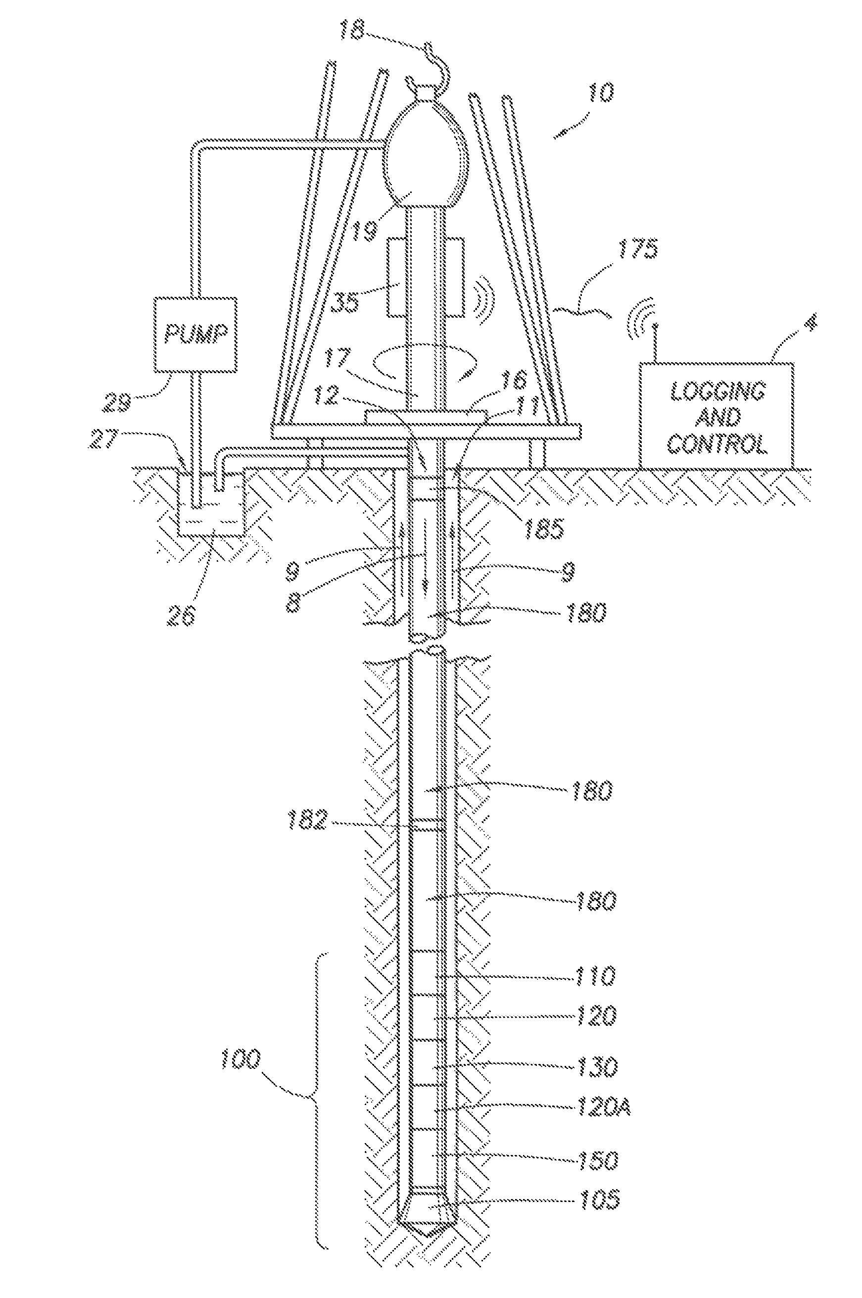
[0035]FIG. 1 illustrates a wellsite system in which the present invention can be employed. The wellsite can be onshore or offshore. In this exemplary system, a borehole 11 is formed in subsurface formations 30 by rotary drilling in a manner that is well known. Embodiments of the invention can also use directional drilling, as will be described hereinafter.

[0036]A drill string 12 is suspended within the borehole 11 and has a bottom hole assembly 100 which includes a drill bit 105 at its lower end. The surface system includes platform and derrick assembly 10 positioned over the borehole 11, the assembly 10 including a rotary table 16, kelly 17, hook 18 and rotary swivel 19. The drill string 12 is rotated by the rotary table 16, energized by means not shown, which engages the kelly 17 at the upper end of the drill string. The drill string 12 is suspended from a hook 18, attached to a traveling block (also not shown), through the kelly 17 and a rotary swivel 19 which permits rotation of...


PUM


Abstract

The disclosure has application for use in conjunction with an operation of drilling an earth borehole using: a drilling rig, a drill string having its generally upper end mechanically coupleable with and suspendable from the drilling rig, and a bottom hole assembly adjacent the lower end the drill string, the bottom hole assembly including a drill bit at its lower end. A method is set forth for obtaining information about at least one parameter sensed at the bottom hole assembly, including the following steps: providing at least one measuring device in the bottom hole assembly, the at least one measuring device producing measurement data representative of a measured condition at the bottom hole assembly; providing an uphole processor system at the earth's surface; providing a drill string telemetry system coupled with the at least one measuring device and coupled with the uphole processor system; and transmitting the data from the measuring device to the uphole processor system via the drill string telemetry system.

Description

PRIORITY CLAIM AND RELATED APPLICATIONS[0001]The present Application claims priority from U.S. Provisional Patent[0002]Application No. 60 / 705,326, filed Aug. 4, 2005, and also claims priority from U.S. Provisional Patent Application No. 60 / 708,561, filed Aug. 16, 2005, and both said U.S. Provisional Patent Applications are incorporated herein by reference. The present Application contains subject matter that relates to subject matter disclosed in copending U.S. patent application Ser. No. 11 / 995,027, titled “Interface and Method for Wellbore Telemetry System” (hereinafter “the '027 Application”) and U.S. patent application Ser. No. 11 / 498,847, titled “Surface Communication Apparatus and Method for Use with Drill String Telemetry” (hereinafter “the '847 application”), both filed on Aug. 3, 2006, and both assigned to the same assignee as the present Application.FIELD OF THE INVENTION[0003]This invention relates to the fields of drilling and producing hydrocarbon wells, and to the meas...

Claims


Application Information

Patent Timeline
Patent Type & Authority Patents(United States)
IPC IPC(8): E21B47/12
CPCE21B17/003E21B17/028E21B47/12E21B47/122G01V11/002E21B47/13E21B17/0283
Inventor LI, QIMINGCLARK, BRIANMEHTA, SHYAM B.HUTIN, REMIREED, CHRISTOPHER P.SANTOSO, DAVIDHVATUM, LISEMADHAVAN, RAGHUFOLLINI, JEAN-MARCDOWNTON, GEOFFREY C.ALDRED, WALTER D.
Owner SCHLUMBERGER TECH CORP
Why Eureka
Try Eureka