Modular suspension system

a suspension system and module technology, applied in the direction of shock absorbers, mechanical equipment, transportation and packaging, etc., can solve the problems of limiting the range of basic alignment specifications, not having much adjustability, and not having much flexibility, so as to achieve easy disassembly and access, high performance, and low maintenance

Inactive Publication Date: 2011-03-29
JME ENTERPRISES
View PDF18 Cites 14 Cited by
  • Summary
  • Abstract
  • Description
  • Claims
  • Application Information

AI Technical Summary

Benefits of technology

[0005]This invention involves a method for manufacturing and using a modular suspension system (“system”) which is high performance, reliable, dependable, effective, low maintenance and structurally sound. The object of the present invention is to provide a suspension system capable of being easily disassembled to access a automobiles engine parts and to allow parts of the system to be easily interchangeable and eliminate defects and drawbacks encountered in the prior art. This suspension also maintains a desired camber angle during various driving maneuvers and roadway conditions. Many pieces of the instant suspension system are bolted together in contrast to conventional suspension systems where these same pieces are welded, cast or otherwise not modular. This modular design has many benefits including the ability to easily access a car's engine, oil pan or other parts without the need to remove the entire suspension or a large portion thereof. The modular construction allows installation of interchangeable parts enabling this suspension to function with different makes and models of vehicles, in differing driving conditions or allowing increased performance for differing forms of driving such as racing or off-road driving.
[0006]This suspension system is attached to the body of the vehicle and in its most basic embodiment is comprised of a right and a left side connected by a front cross member, a rear cross member and a sway bar. Each the right and left side has at a minimum upper control arms, modular lower control arms, a hub, steering arm, brake mount, cradle brace, cradle mount, rear cradle support, lower shock mount, upper shock mount, modular motor mount, axle, rack bushing, spindle, shock, rocker mount, axle shaft and frame mount locator thus making the entire suspension system have two of each of these parts. In alternate embodiments the system can also have push rods, a rocker, lay down shock mount, and rocker mount. This suspension system has many benefits over standard suspensions. Some of the parts which are novel are the control arms, the motor mounts, the spindles, the sway bar, cross members, the upper shock mount and the rocker shock design and configuration. The suspension is a double wishbone design which replaces the inferior strut suspension. All of the geometry of this suspension system is optimized for unsurpassed handling and performance. It has zero bump steer and is tested and proven on the racetrack. The spindles incorporate a two inch drop in ride height to maintain proper suspension geometry. The upper control arm is off set back of lower control arm which creates static positive caster. This suspension can be built in conventional shock configuration (upright shock) or rocker set-up (cantilever push-rod design). There are three positions of the adjustable anti-roll bar which provides for wide range of adjustability. The spherical bearings which add many additional benefits to the system which will be explained in detail below and are self-lubricating thus requiring no maintenance.
[0007]The motor mount of this suspension uses a spherical bearing or ball joint which allows the engine and transmission assembly to be articulated in the proper driveline angle for the particular vehicle. The spherical bearings of the motor mount also allow the motor to be articulated for easier transmission removal and installation. The center section(s) of the cross member or k-member is removable so that the user can easily access the oil pain and remove it if necessary.

Problems solved by technology

While versatile, these systems are not of modular design and generally do not have much adjustability limiting the range for basic alignment specifications especially for performance or racing applications.
None are of a modular design that would allow a wider range of application, reduction in costs and more adjustability.

Method used


Image

  • Modular suspension system
  • Modular suspension system
  • Modular suspension system

Examples


Embodiment Construction

[0036]After reading this description it will become apparent to one skilled in the art how to implement the invention in various alternative embodiments and alternative applications. However, all the various embodiments of the present invention will not be described herein. It is understood that the embodiments presented here are presented by way of an example only, and not limitation. As such, this detailed description of various alternative embodiments should not be construed to limit the scope or breadth of the present invention as set forth below.

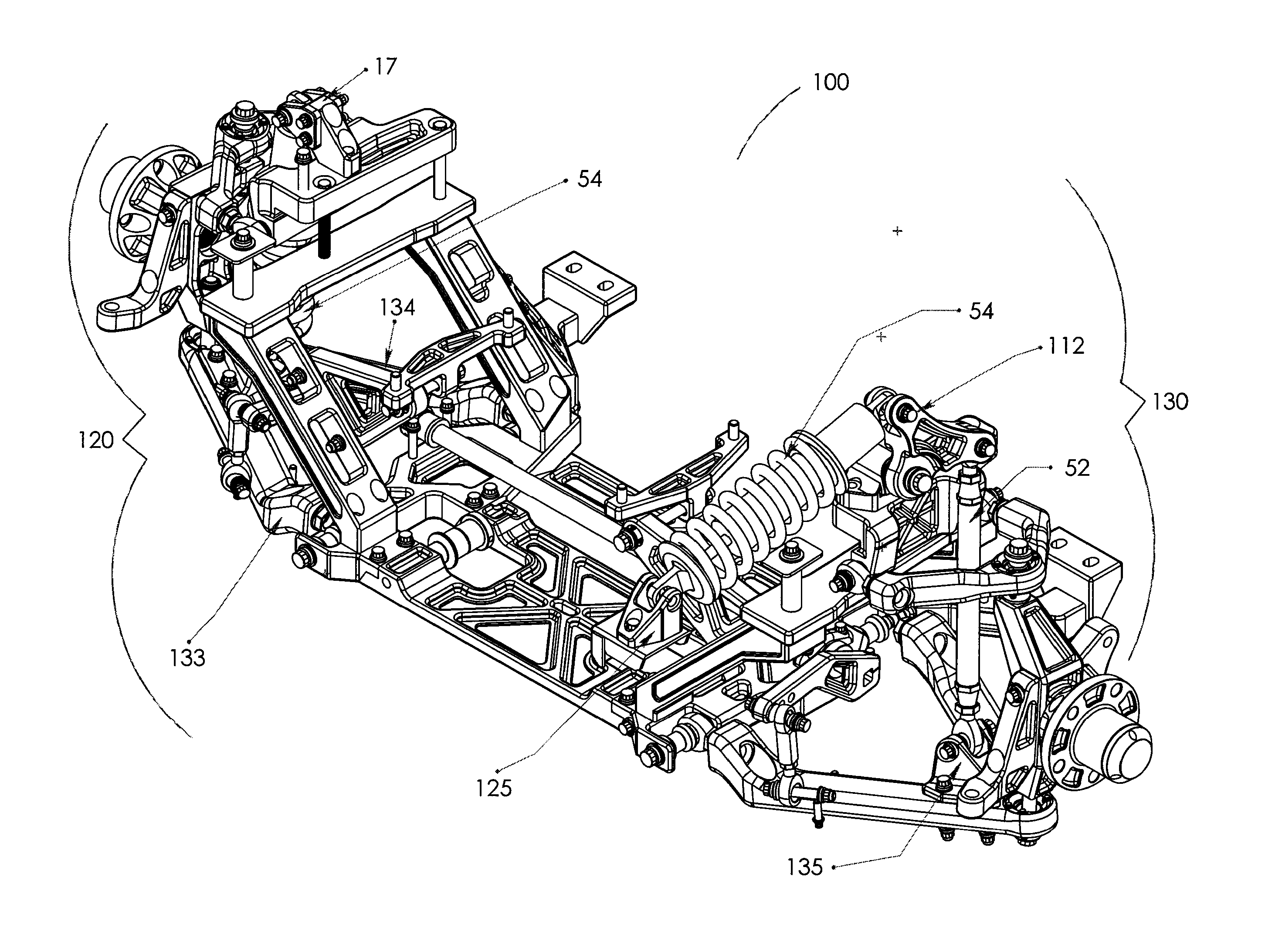
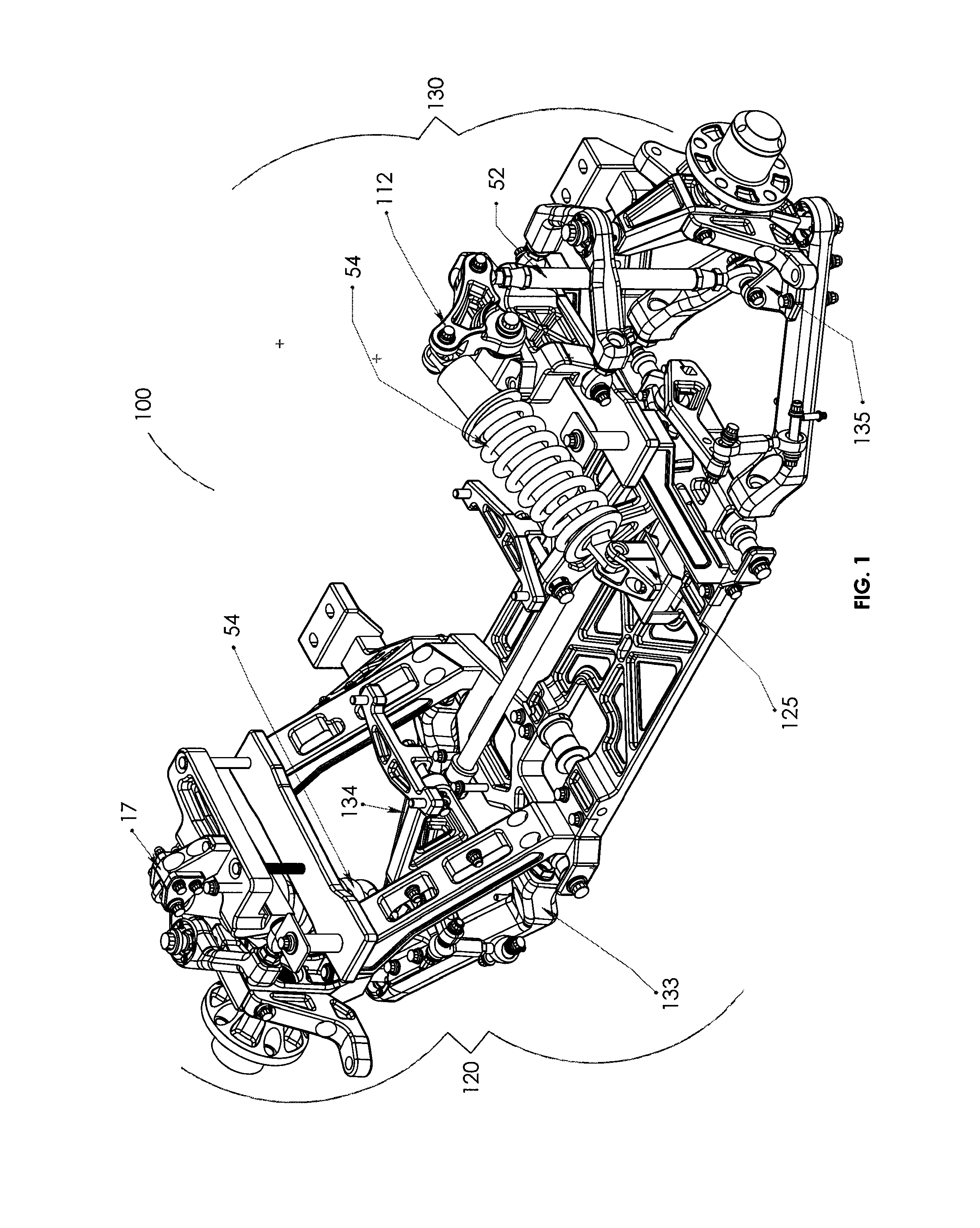
[0037]With reference to FIG. 1 a modular suspension system (“system”) 100 is shown and displayed. This invention involves a suspension system 100 which is modular. The suspension has a right 130 and a left side 120. Each side is essentially a mirror of the other in that the parts are assembled in the same configuration on each side. The benefit to modular construction is that the components of the sides can be configured or assembled di...


PUM


Abstract

A modular suspension system for automobiles and trucks. The present invention relates to a suspension system which is both modular in design and specifically manufactured for high performance wheeled vehicles. This system has multiple modular parts which enable the system to function in various makes and models of vehicles. The modular aspects of this system also enable the cradle to be removable so that the engine and transmission of the vehicle can be easily reached. The modular aspects also allow this system to be set-up with a traditional shock configuration or with a rocker set-up shock system.

Description

FIELD OF THE INVENTION[0001]The present invention relates, in general, to a modular suspension system for automobiles and trucks. More particularly, the present invention relates to a system which is both modular in design and specifically manufactured for high performance wheeled vehicles.BACKGROUND OF THE INVENTION[0002]Suspension systems have been in existence since the automobile was invented. These systems enable automobiles to absorb shock stay in line when driving and essentially hold vehicle to the road. There are many different types of suspension systems one is a Macphereson strut suspension which is the standard in most passenger vehicles currently due to the cost effectiveness and ease of assembly while on the production line for the vehicle manufacturer.[0003]The are many other types of suspensions systems include but are not limited to, traditional double wish bone, multi link, trailing arm, linked and dependent systems. While versatile, these systems are not of modula...

Claims


Application Information

Patent Timeline
Patent Type & Authority Patents(United States)
IPC IPC(8): B60G7/02
CPCB60G3/20B60G7/001B60G2200/144B60G2204/15B60G2204/421B60G2206/0114B60G2206/60B60G2206/606
Inventor MAYEN, JULIO WERNERBUCH, TERRY CURTIS
Owner JME ENTERPRISES
Why Eureka
Try Eureka