Eureka AIR delivers breakthrough ideas for toughest innovation challenges, trusted by R&D personnel around the world.

Light emitting display device and method of fabricating the same

a technology of light-emitting display and light-emitting silicon, which is applied in the direction of radiation control devices, semiconductor devices, electrical apparatuses, etc., can solve the problems of low light-emitting efficiency of conventional pd, high power consumption of led, and low light-emitting efficiency of polycrystalline silicon, etc., to improve light-emitting efficiency and light-emitting efficiency.

Active Publication Date: 2011-03-29
SAMSUNG DISPLAY CO LTD
View PDF11 Cites 2 Cited by
  • Summary
  • Abstract
  • Description
  • Claims
  • Application Information

AI Technical Summary

Benefits of technology

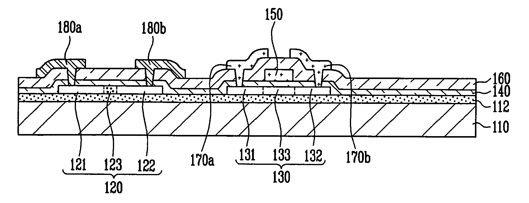
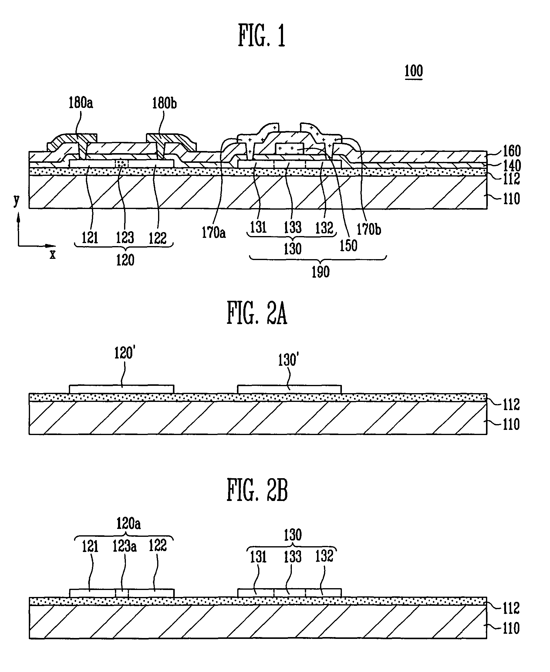
[0007]It is therefore a feature of an embodiment of the present invention to provide a light emitting display device with a PD having improved light receiving efficiency.
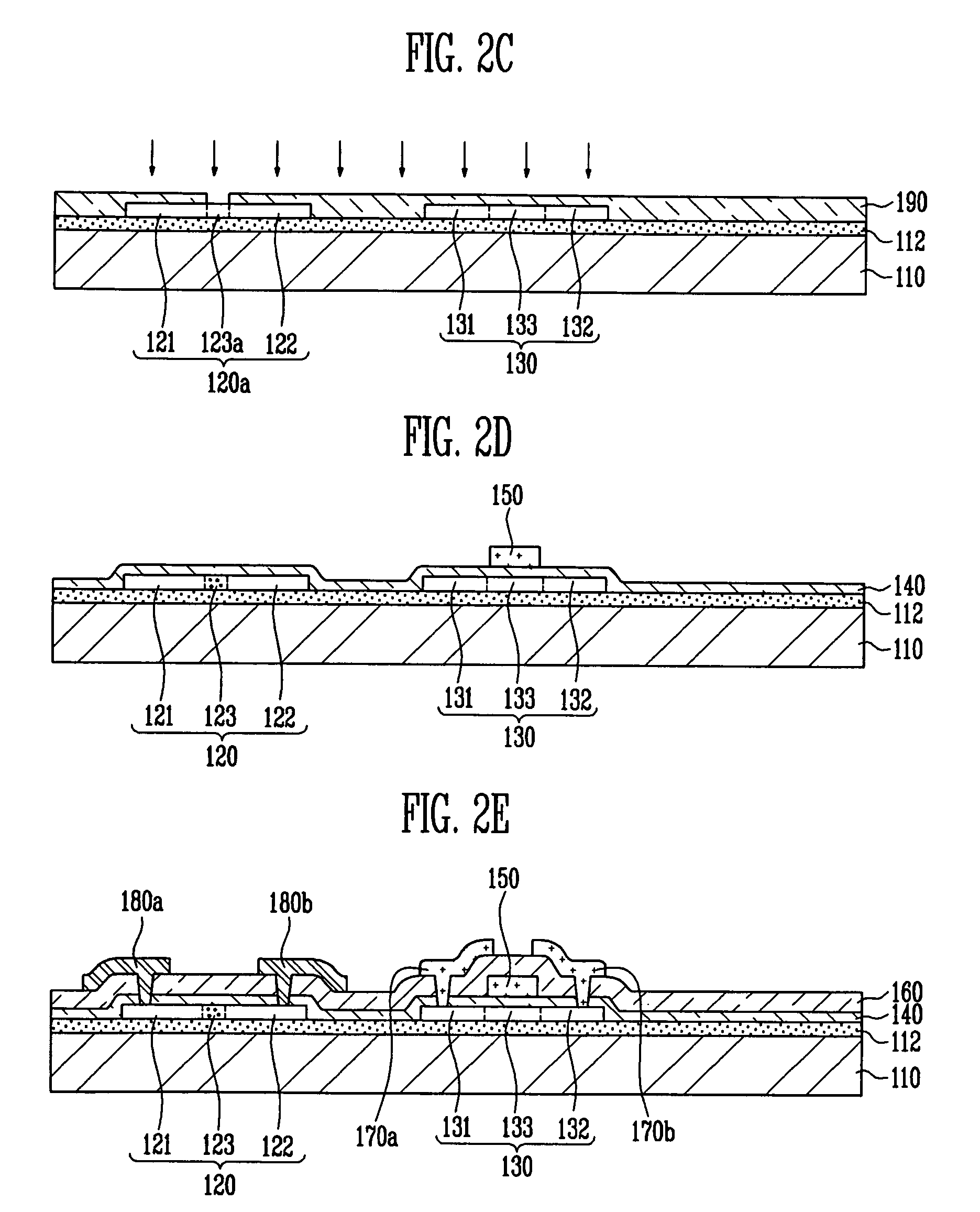
[0008]It is therefore another feature of an embodiment of the present invention to provide a method of fabricating a light emitting display device with a PD having improved light receiving efficiency.

Problems solved by technology

The LED, however, may have high power consumption due to a constant luminance value thereof regardless of changes in ambient light.
The polycrystalline silicon may have a relatively low light sensitivity, so light receiving efficiency of the conventional PD may be relatively low.
The low light receiving efficiency of the PD may generate an insufficient amount of electrical signals, so luminance control of the LED may be difficult.

Method used


Image

  • Light emitting display device and method of fabricating the same
  • Light emitting display device and method of fabricating the same
  • Light emitting display device and method of fabricating the same

Examples


Embodiment Construction

[0017]Korean Patent Application No. 10-2007-0093632, filed on Sep. 14, 2007, in the Korean Intellectual Property Office, and entitled: “Light Emitting Display Device and Method of Fabricating the Same,” is incorporated by reference herein in its entirety.

[0018]Embodiments of the present invention will now be described more fully hereinafter with reference to the accompanying drawings, in which exemplary embodiments of the invention are illustrated. Aspects of the invention may, however, be embodied in different forms and should not be construed as limited to the embodiments set forth herein. Rather, these embodiments are provided so that this disclosure will be thorough and complete, and will fully convey the scope of the invention to those skilled in the art.

[0019]In the figures, the dimensions of layers, elements, and regions may be exaggerated for clarity of illustration. It will also be understood that when a layer or element is referred to as being “on” another layer, element, ...


PUM


Abstract

A light emitting display device includes a light emitting diode and a thin film transistor on a substrate, the light emitting diode and thin film transistor being electrically coupled to each other, and a photo diode on the substrate, the photo diode including an N-type doping region, a P-type doping region, and an intrinsic region between the N-type doping region and the P-type doping region, the intrinsic region including amorphous silicon.

Description

BACKGROUND OF THE INVENTION[0001]1. Field of the Invention[0002]Embodiments of the present invention relate to a light emitting display device and a method of fabricating the same. More particularly, embodiments of the present invention relate to a light emitting display device with a photo diode and to a method of fabricating the same.[0003]2. Description of the Related Art[0004]A light emitting display device may include a light emitting diode (LED) that emits visible light to display images. The LED, however, may have high power consumption due to a constant luminance value thereof regardless of changes in ambient light. Therefore, attempts have been made to use a photo diode (PD) to control luminance of the LED. The PD may convert light energy, e.g., light emitted from the LED or ambient light, into an electrical signal, e.g., electric current or voltage, by generating electrons or holes in accordance with an optical absorption, e.g., intensity of light.[0005]The conventional PD...

Claims


Application Information

Patent Timeline
Patent Type & Authority Patents(United States)
IPC IPC(8): H01L27/148
CPCH01L27/3269H01L27/1214H10K59/13H01L31/10
Inventor IM, KI-JUCHOI, BYOUNG-DEOG
Owner SAMSUNG DISPLAY CO LTD
Why Eureka
Eureka Blog
Learn More