
Method for generation of an image in contrast agent-supported MR angiography and magnetic resonance apparatus

a technology of contrast agent and angiography, which is applied in the field of angiographic image generation, can solve the problems of difficult assessment for users, detection that is not recognized, and is not possible to complete the acquisition of measurement data, and achieves the effect of simple, fast and automatic method, and fast, simple and automatic implementation

Inactive Publication Date: 2011-03-29
SIEMENS HEALTHCARE GMBH
View PDF5 Cites 5 Cited by
  • Summary
  • Abstract
  • Description
  • Claims
  • Application Information

AI Technical Summary

Benefits of technology

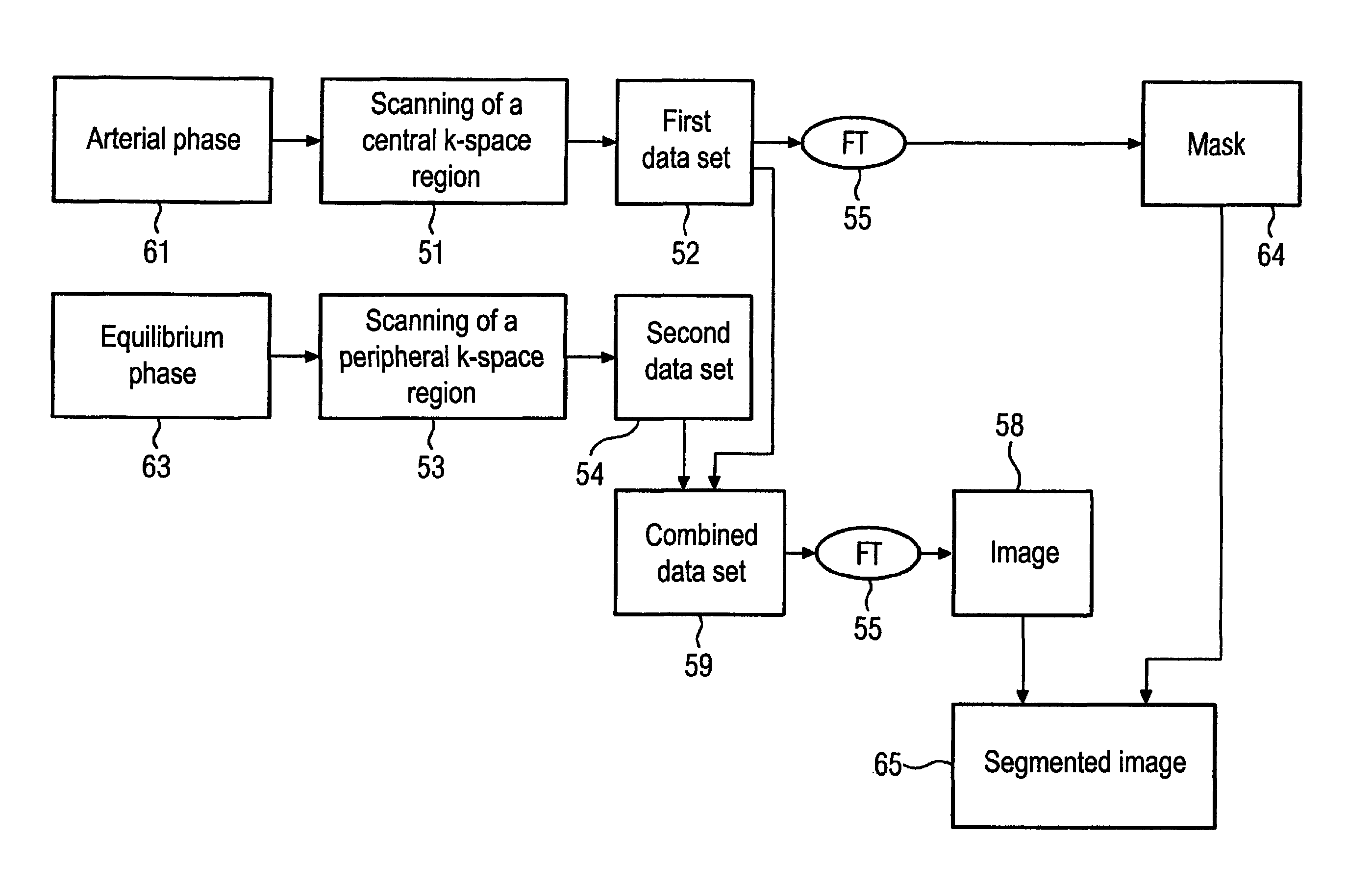
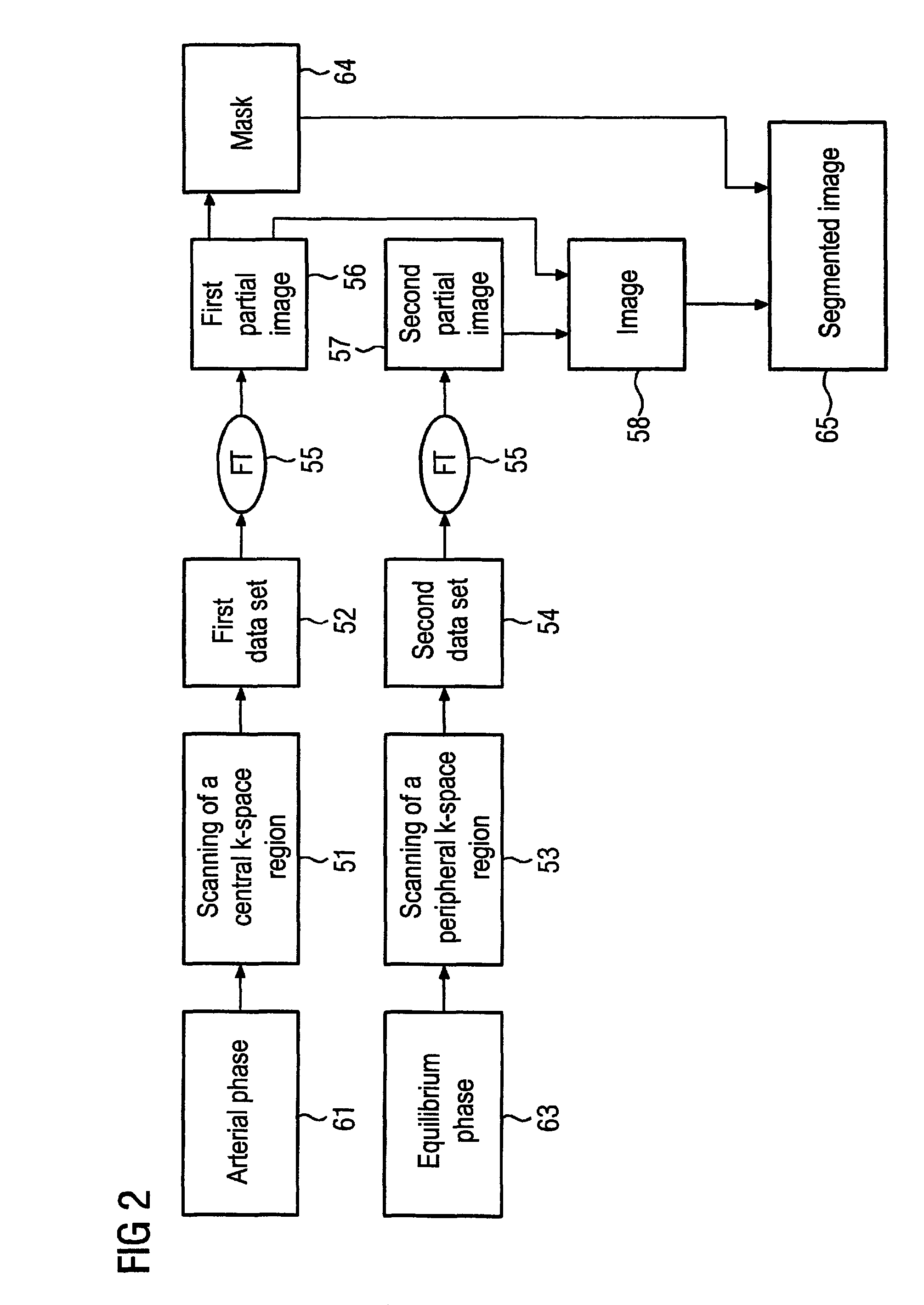
The invention provides a method for generating an image in magnetic resonance angiography (MRA) using a contrast agent that can be used for the simultaneous visualization of arteries and veins in a single image. The method involves acquiring data sets during the arterial and equilibrium phases of the contrast agent distribution, and merging them to create an image with high resolution and high contrast. The method is simple, fast, and automatic, and can be implemented without user interaction. The resulting image allows for the differentiation of arteries and veins, which is useful in diagnostic applications. The invention also includes a magnetic resonance angiography apparatus that supports the method.

Problems solved by technology

An angiography image in which both the arterial portion and the venous portion of the vessel system are imaged in a comparable manner is typically hard for a user to assess with regard to detecting pathologies, since the superimposition of arterial and venous structures often makes the pathologies to be detected unrecognizable.
Given the generation of an angiogram by contrast agent-supported MR technology, a further problem occurs in the representation of the arterial phase.
Since the MR technique requires relatively long image data acquisition times that can exceed the duration of the arterial phase of the contrast agent passage, it is often not possible to be able to complete the acquisition of the measurement data within the arterial phase, such that various methods exist that divide the measurement data to be acquired in different ways.

Method used


Image

  • Method for generation of an image in contrast agent-supported MR angiography and magnetic resonance apparatus
  • Method for generation of an image in contrast agent-supported MR angiography and magnetic resonance apparatus
  • Method for generation of an image in contrast agent-supported MR angiography and magnetic resonance apparatus

Examples


Embodiment Construction

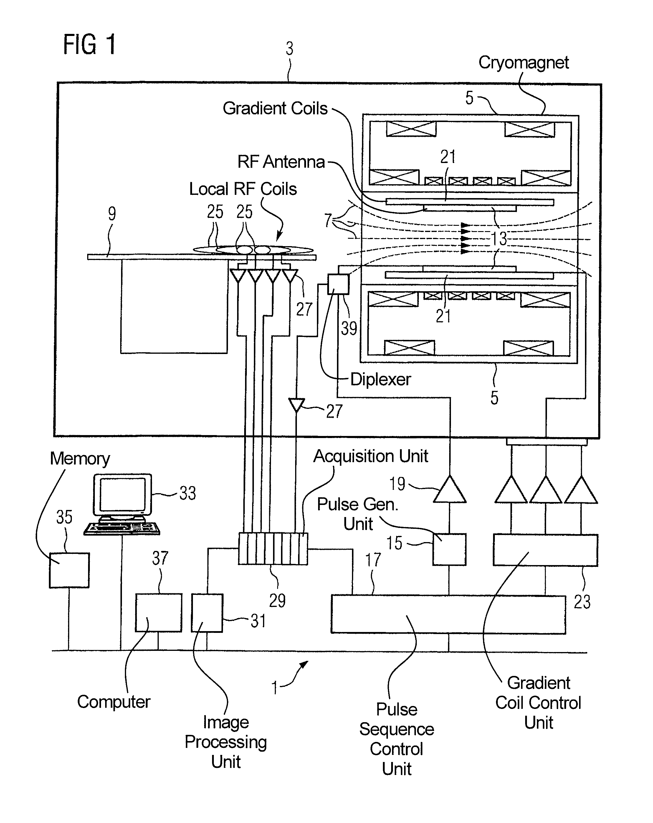
[0030]FIG. 1 schematically shows the design of a magnetic resonance apparatus 1 with its basic essential components. In order to examine a body by means of magnetic resonance imaging, various magnetic fields matched as precisely as possible to one another in terms of their temporal and spatial characteristics are applied.

[0031]A strong magnet (typically a cryomagnet 5 with a tunnel-shaped opening) arranged in a radio frequency-shielded measurement chamber 3 generates a strong, static basic magnetic field 7 that is typically 0.2 Tesla to 3 Tesla and more. A body or a body part (not shown here) to be examined is placed on a patient bed 9 and positioned in a homogeneous region of the basic magnetic field 7.

[0032]The excitation of the nuclear spins of the body ensues by radio-frequency excitation pulses that are radiated via a radio-frequency antenna (shown here as a body coil 13). The radio-frequency excitation pulses are generated by a pulse generator 15 that is controlled by a pulse ...


PUM


Abstract

In a method and apparatus for generation of an image in contrast agent-supported magnetic resonance angiography, a first data set is generated during an arterial phase of a distribution of a contrast agent in a vessel system by scanning of a first central k-space region, a second data set is generated during an equilibrium phase of the distribution of the contrast agent in the vessel system by scanning a peripheral k-space region while omitting scanning of a second central region, and the image is generated by merging the first data set and the second data set.

Description

BACKGROUND OF THE INVENTION[0001]1. Field of the Invention[0002]The present invention concerns a method for generation of an angiographic image using magnetic resonance technology in which the contrast of vessel structures is intensified by a contrast agent. The invention also concerns a magnetic resonance apparatus for implementing such a method.[0003]2. Description of the Prior Art[0004]Magnetic resonance technology has been increasingly used for generation of angiographic images since, relative to other medical imaging methods (such as, for example, radioscopy with x-rays or computed tomography) it exhibits, among other things, the advantage that patient and medical personnel are subject to no radiation exposure.[0005]Magnetic resonance (MR) technology is a known technique with which images of the inside of an examination subject can be generated. The examination subject is positioned in a comparably strong, static, homogeneous basic magnetic field (field strength of 0.2 Tesla to...

Claims


Application Information

Patent Timeline
Patent Type & Authority Patents(United States)
IPC IPC(8): A61B5/05
CPCG01R33/5601G01R33/5635G01R33/281G01R33/4818
Inventor KIRSCH, RAINER
Owner SIEMENS HEALTHCARE GMBH
Learn More