Method for production of a three-dimensional curved fiber composite material structural component

a fiber composite material and structural component technology, applied in weaving, efficient propulsion technologies, other domestic articles, etc., can solve the problems of difficult placement of unidirectional tapes into flanges, lowering of fiber-parallel compressive strength, etc., and achieves the effect of little production effort and good

Inactive Publication Date: 2011-04-05
AIRBUS HELICOPTERS DEUT GMBH
View PDF17 Cites 4 Cited by
  • Summary
  • Abstract
  • Description
  • Claims
  • Application Information

AI Technical Summary

Benefits of technology

[0010]An object of the present invention is to provide a method for the production of a three-dimensionally curved fiber composite material structural component, for example, a former or spar in airplane or helicopter construction, which—with little production effort—makes it possible to bring the unidirectional fibers and the fiber laid scrim into a three-dimensional shape in which the desired fiber orientation in the individual areas is ensured.

Problems solved by technology

In addition to the unidirectional laid scrim for the flanges, the fiber composite material structural component comprises the shear web that is made of a woven fabric or of a laid scrim, whereby in the case of a woven fabric, an undulation of the fibers is created by the weaving and this can lead to a lowering of the fiber-parallel compressive strength.
As an alternative, so-called binder preforming is used with which, however, the placement of unidirectional tapes into the flanges is difficult.

Method used


Image

  • Method for production of a three-dimensional curved fiber composite material structural component
  • Method for production of a three-dimensional curved fiber composite material structural component

Examples


Embodiment Construction

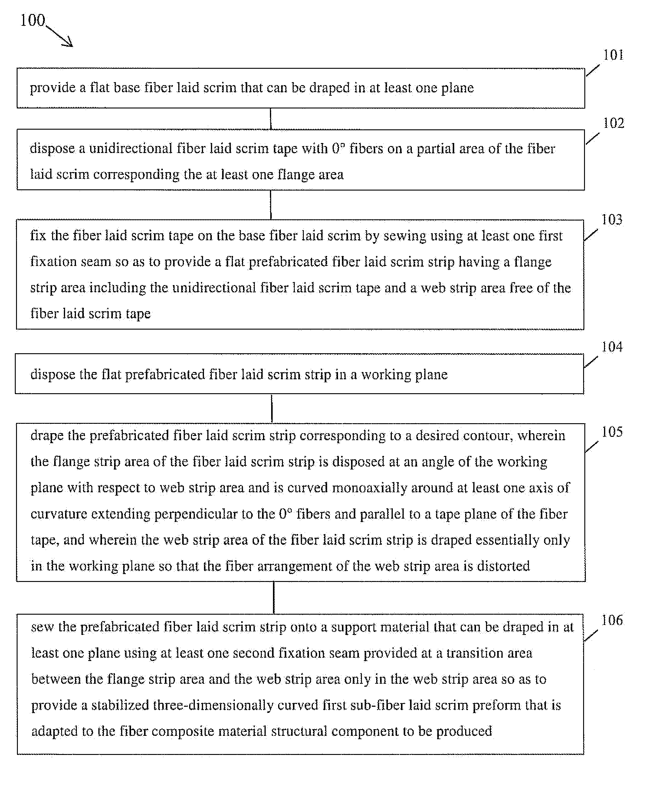
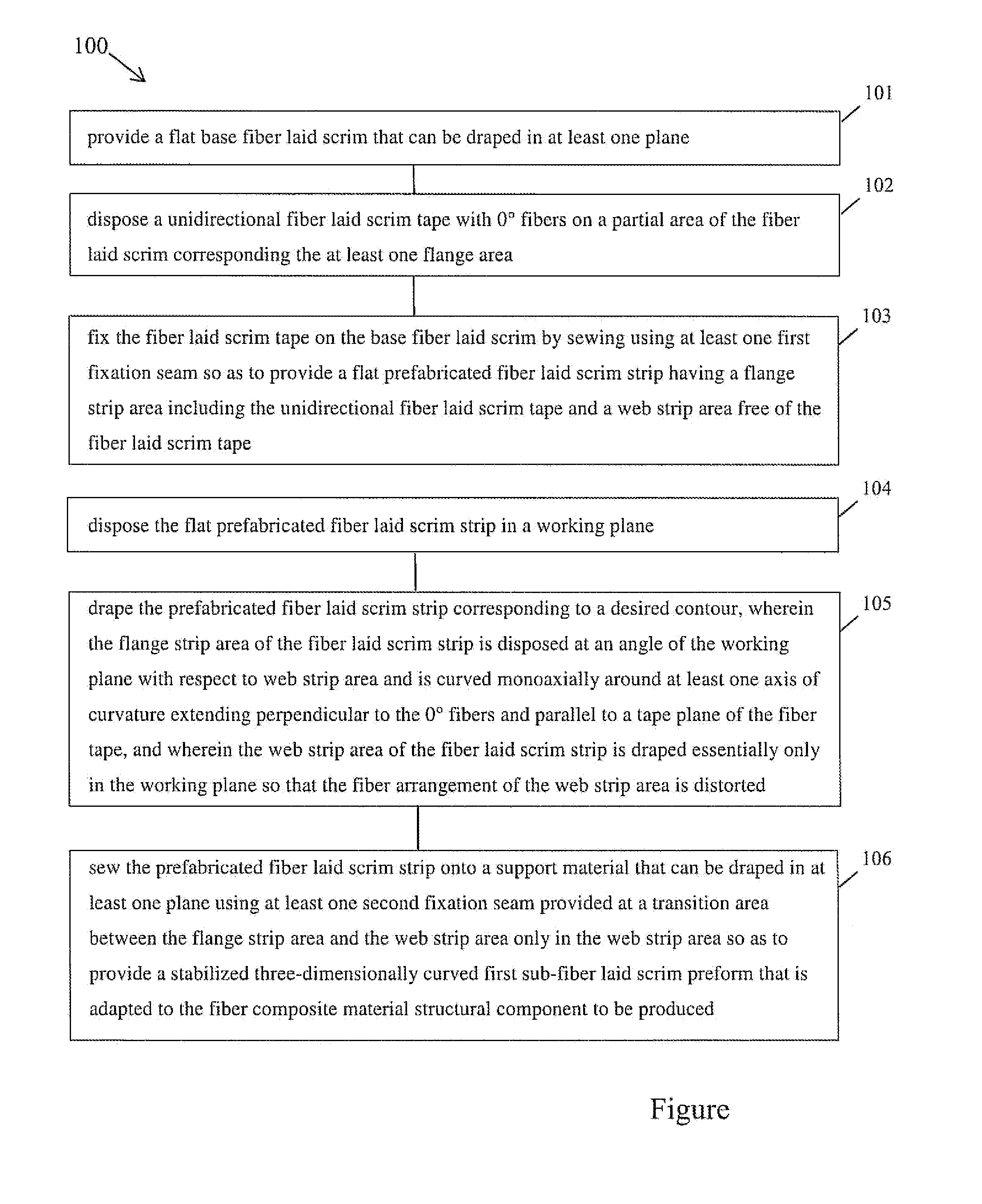
[0020]The FIGURE shows a schematic flow diagram of a method 100 for producing a three-dimensionally curved fiber composite material structural component having a predefined flexural member profile cross section with at least one web area and at least one adjacent flange area. In block 101 a flat base fiber laid scrim that can be draped in at least one plane is provided. In block 102, a unidirectional fiber laid scrim tape with 0° fibers is disposed on a partial area of the fiber laid scrim which lies in the at least one flange area of the fiber composite material structural component to be produced. In block103, the fiber laid scrim tape is fixed on the base fiber laid scrim by sewing using at least one first fixation seam to create a flat prefabricated fiber laid scrim strip that has a flange strip area containing the unidirectional fiber laid scrim tape and a web strip area that is free of the unidirectional fiber laid scrim tape. In block 104, the flat prefabricated fiber laid sc...


PUM

PropertyMeasurementUnit
angleaaaaaaaaaa
angleaaaaaaaaaa
angleaaaaaaaaaa

Abstract

A method for producing a three-dimensionally curved fiber composite material component having a predefined flexural member profile cross section with at least one web area and at least one adjacent flange area, includes providing a flat base fiber laid scrim and disposing a unidirectional fiber laid scrim tape with 0 degree fibers on a partial area of the fiber laid scrim and fixed by sewing so as to provide a flat prefabricated fiber laid scrim strip having a flange area including the unidirectional fiber laid scrim tape and a web strip area free of the fiber laid scrim. The prefabricated scrim tape is draped to a desired contour and is sewn onto a support material so as to provide a stabilized three-dimensionally curved first sub-fiber laid scrim preform adapted to the fiber composite material structural component to be produced.

Description

[0001]This application is a U.S. National Phase application under 35 U.S.C. §371 of International Application No. PCT / EP2006 / 001229, filed Jul. 15, 2006 and claims the benefit of German Patent Application Nos. DE 10 2005 003498, filed on Jul. 19, 2005 and 10 2006 031491, filed Jul. 6, 2005. The International Application was published in German on Jan. 25, 2007 as WO 2007 / 009440 under PCT Article 21 (2).[0002]The present invention relates to a method for the production of a three-dimensionally curved fiber composite material structural component. Such fiber composite material structural components are used, for example, as spars or formers, that is to say, as load-bearing components of an aircraft wing. The beam-shaped spar has the function of absorbing the lateral forces and flexural moments stemming from the aerodynamic and inertial forces. Spars are also used, for example, in rotor blades, for example, of wind turbines and helicopters. Moreover, spars, spars formers consisting of ...

Claims


Application Information

Patent Timeline
Patent Type & Authority Patents(United States)
IPC IPC(8): D05B35/06D04H1/74B32B37/14B29D99/00
CPCB29B11/16B29C70/30B29C70/543B29D99/0003Y10T428/24033B29L2031/08B29L2031/3076Y02T50/433Y10T442/186Y02T50/40B29C70/54B29D99/00
Inventor WEIMER, CHRISTIAN
Owner AIRBUS HELICOPTERS DEUT GMBH
Why Eureka
Try Eureka