Method for training dynamic random access memory (DRAM) controller timing delays

a dynamic random access memory and controller technology, applied in the field of dynamic random access memory (dram) controllers, can solve the problems of signal propagation delays between the dram controller and the memory chips that can exceed one memory clock (memclk) cycle, and it is difficult to establish a proper delay for the dll

Active Publication Date: 2011-04-12
ADVANCED MICRO DEVICES INC
View PDF34 Cites 26 Cited by
  • Summary
  • Abstract
  • Description
  • Claims
  • Application Information

AI Technical Summary

Problems solved by technology

Topological and electrical difference between DQ and DQS interconnects result in timing skew between these signals, making it difficult to establish a proper delay for the DLL.
These speeds are now so high that signal propagation delays between the DRAM controller and the memory chips can exceed one memory clock (MEMCLK) cycle.
At such high speeds, training the timing delays becomes more difficult.

Method used


Image

  • Method for training dynamic random access memory (DRAM) controller timing delays
  • Method for training dynamic random access memory (DRAM) controller timing delays
  • Method for training dynamic random access memory (DRAM) controller timing delays

Examples


Embodiment Construction

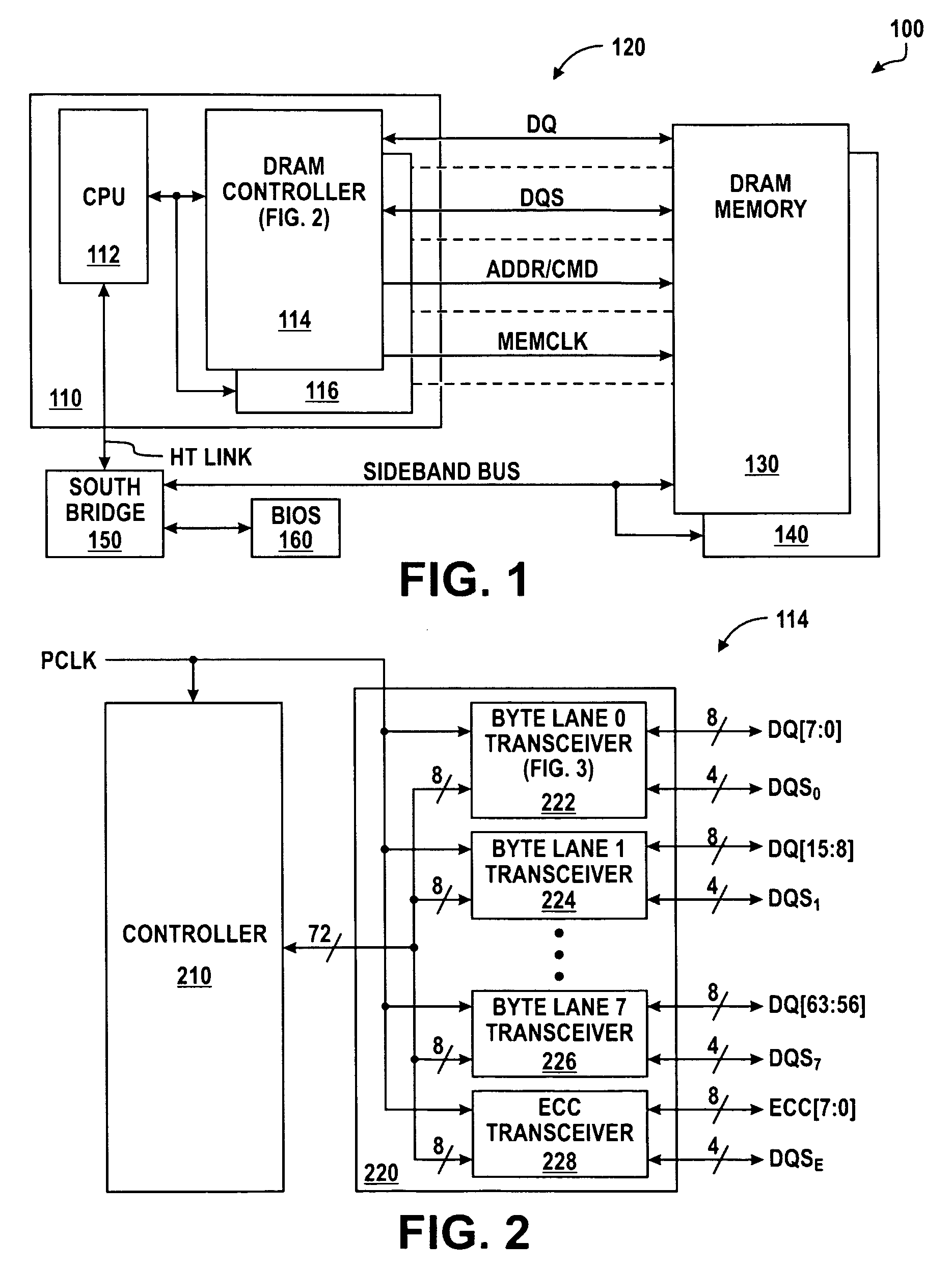
[0027]FIG. 1 illustrates in block diagram form a data processing system 100 according to the present invention. Data processing system 100 includes generally a microprocessor 110, a memory interface 120, memories 130 and 140, a south bridge 150, and a basic input / output system (BIOS) memory 160. Microprocessor 110 includes generally a central processing unit (CPU) 112, and dynamic random access memory (DRAM) controllers 114 and 116. CPU 112 has a bidirectional interface to DRAM controllers 114 and 116 for conducting address, data, and control signals, and a terminal connected to an external bidirectional interface labeled “HT LINK.” The HT LINK is a high-speed link that conforms to the non-coherent link protocol specification promulgated by the HyperTransport Consortium. DRAM controllers 114 and 116 are also connected to memory interface 120 and each has an input / output terminal for conducting a memory data signal labeled “DQ,” an input / output terminal for conducting a memory data s...


PUM


Abstract

Timing delays in a double data rate (DDR) dynamic random access memory (DRAM) controller (114, 116) are trained. A left edge of passing receive enable delay values is determined (530). A final value of a receive data strobe delay value and a final value of a transmit data delay value are trained (540). A right edge of passing receive enable delay values is determined using a working value of the receive data strobe delay (550); and a final receive enable delay value intermediate between the left edge of passing receive enable delay values and the right edge of passing receive enable delay values is set (560).

Description

CROSS REFERENCE TO RELATED APPLICATIONS[0001]Related subject matter is contained in the following copending applications:[0002]Application Ser. No. 12 / 059,613, filed Mar. 31, 2008, entitled “CIRCUIT USING A SHARED DELAY LOCKED LOOP (DLL) AND METHOD THEREFOR” invented by Shawn Searles, Nicholas T. Humphries, and Faisal A. Syed and assigned to the assignee hereof.[0003]Application Ser. No. 12 / 059,593, filed Mar. 31, 2008, entitled “CIRCUIT FOR LOCKING A DELAY LOCKED LOOP (DLL) AND METHOD THEREFOR” invented by Shawn Searles, Nicholas T. Humphries, and Faisal A. Syed and assigned to the assignee hereof.[0004]Application Ser. No. 12 / 059,641, filed Mar. 31, 2008, entitled “DATA DRIVER CIRCUIT FOR A DYNAMIC RANDOM ACCESS MEMORY (DRAM) CONTROLLER OR THE LIKE AND METHOD THEREFOR” invented by Shawn Searles, Nicholas T. Humphries, and Faisal A. Syed and assigned to the assignee hereof.[0005]Application Ser. No. 12 / 127,059, filed May 27, 2008, entitled “METHOD AND APPARATUS FOR IMPLEMENTING WRI...

Claims


Application Information

Patent Timeline
Patent Type & Authority Patents(United States)
IPC IPC(8): G11C7/00
CPCG11C7/1051G11C7/106G11C7/1066G11C7/1078G11C7/1087G11C7/1093G11C7/22G11C7/222G11C11/4072G11C11/4076G11C11/4093G11C7/20G11C2207/2254G11C29/023G11C29/028
Inventor SEARLES, SHAWNASKAR, TAHSINHAMILTON, THOMAS H.HOUSTY, OSWIN
Owner ADVANCED MICRO DEVICES INC
Why Eureka
Try Eureka