
Ice management system for rotary-wing aircraft

a technology for rotary-wing aircraft and ice management, which is applied in the direction of liquid fuel engines, marine propulsion, and vessel construction, etc., can solve the problems of low emi, helicopters are not equipped with ice protection devices such as de-ice and/or anti-ice components, and the types of ice management components, such as inflatable boots, are inappropriate for helicopter use, etc., to achieve low emi and reduce complexity

Active Publication Date: 2011-04-19
TEXTRON INNOVATIONS
View PDF11 Cites 11 Cited by
  • Summary
  • Abstract
  • Description
  • Claims
  • Application Information

AI Technical Summary

Benefits of technology

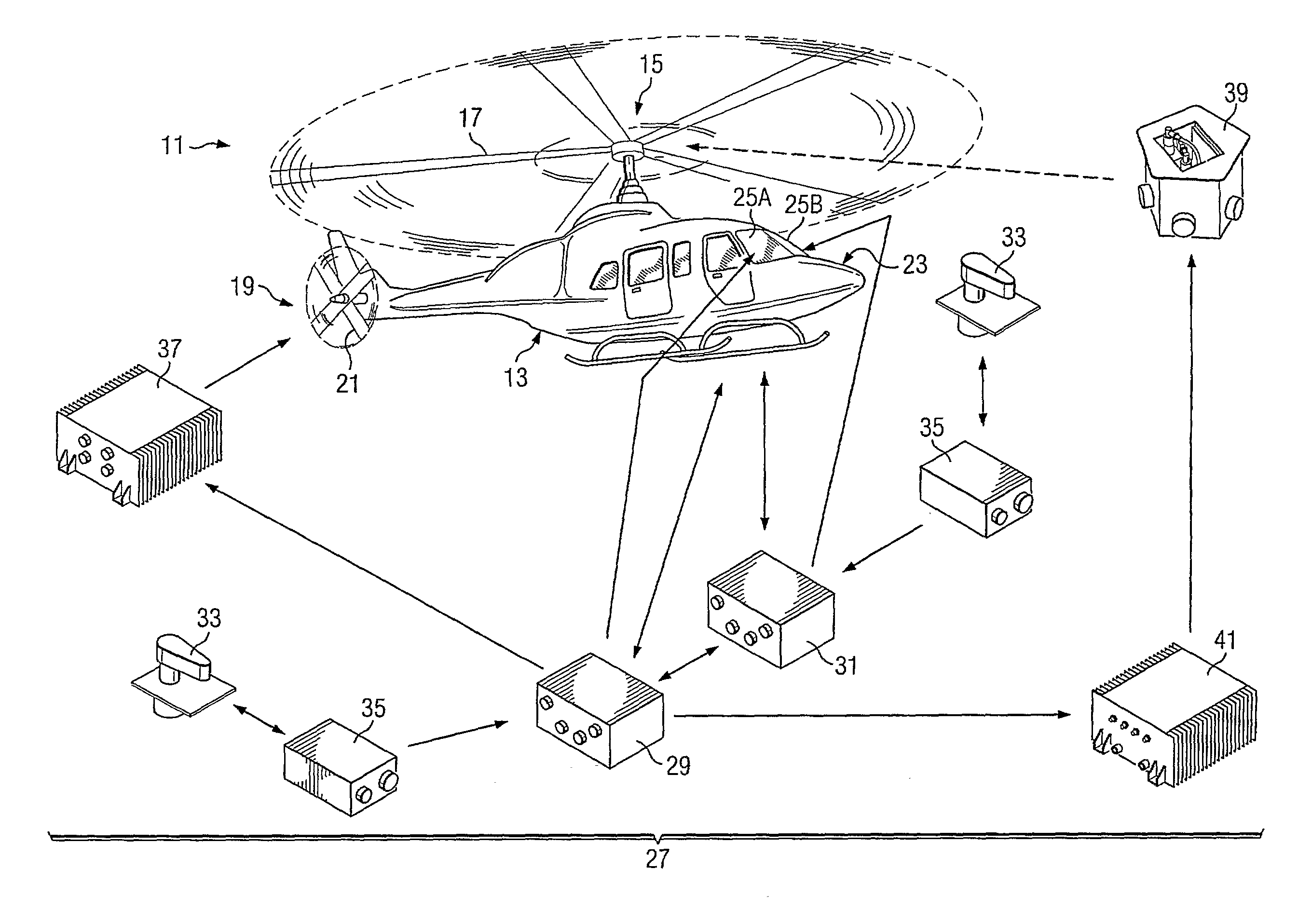
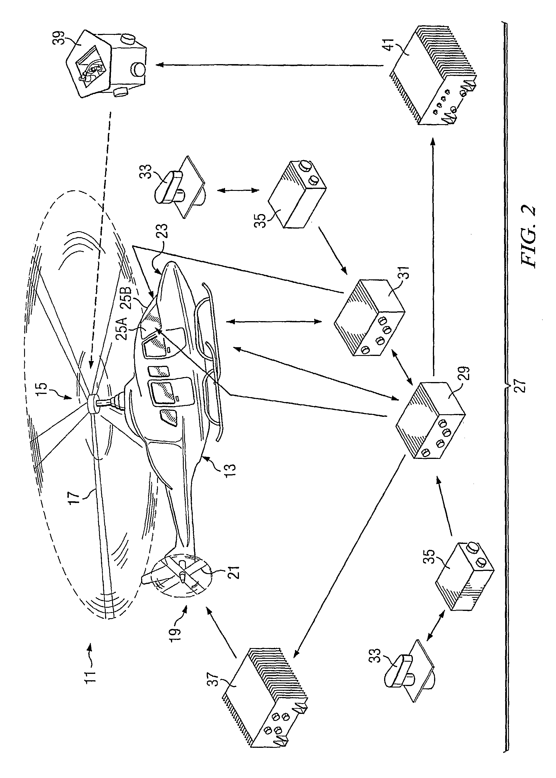
The present invention provides an ice management system for a rotary-wing aircraft that can be used with rotors having any number of blades. The system uses computer-based processors to control the operation of heating elements located on the blades of at least one rotor. The system has many advantages, including reduced complexity, a balanced 3-phase AC load, the ability to use low-cost components, low levels of EMI, compact size, low weight, and increased reliability.

Problems solved by technology

While ice management systems have used on various fixed-wing aircraft for many years, few ice management systems for rotary-wing aircraft, such as helicopters and tiltrotors, have been disclosed.
Typically, helicopters are not equipped with ice protection devices, such as de-ice and / or anti-ice components, due to their weight, complexity, and / or cost.
In addition, some types of ice management components, such as inflatable boots, are inappropriate for use on helicopters.
However, generating and controlling the delivery of electrical power to the ice management systems must be done with concern for the size and weight of components.
Every additional component takes up space that could alternatively be used for other equipment required for flight, leading to reduced cabin size or increased size of the aircraft.
However, systems using this type of power are not easily adapted to rotors having a number of blades that is not a multiple of 3.
For example, in providing 3-phase power to a helicopter with 5 rotor blades, one phase per rotor blade in a “Y” load configuration introduces a load imbalance because 5 is not an even multiple of 3, and the same problem exists when providing two phases in the case of a delta load configuration.
This causes a load imbalance for the AC generator which is not desirable in modern generating systems.

Method used


Image

  • Ice management system for rotary-wing aircraft
  • Ice management system for rotary-wing aircraft
  • Ice management system for rotary-wing aircraft

Examples


Embodiment Construction

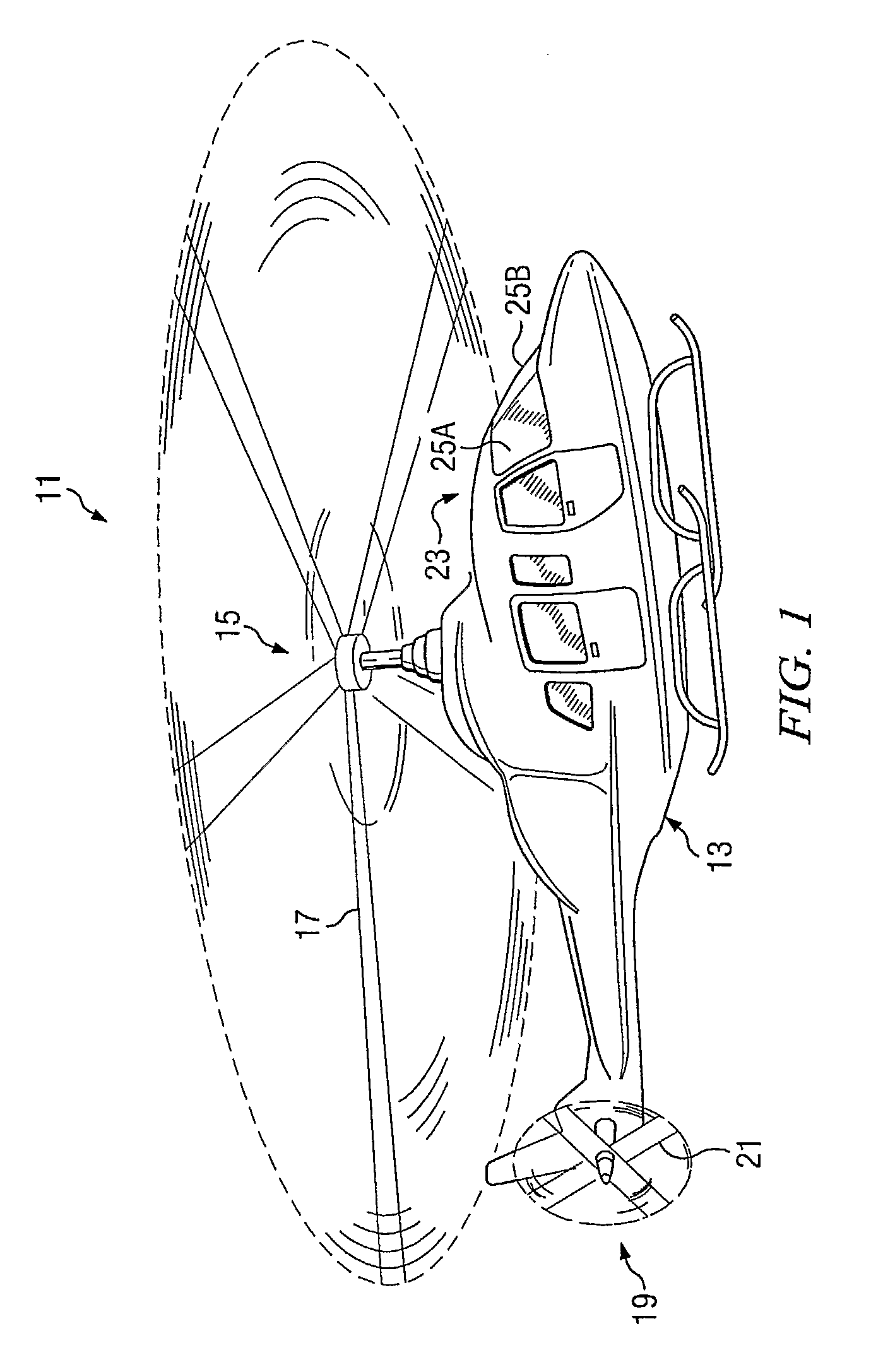
[0022]The present invention is an ice management system for rotary-wing aircraft, having a 3-phase alternating-current (AC) power generation system. The system is especially useful on aircraft having at least one rotor with a number of blades that is not a multiple of 3, including both main and tail rotors of helicopters and prop-rotors of tiltrotor aircraft.

[0023]The system incorporates ice protection devices, such as anti-ice and / or de-ice components, carried by the blades of the rotors, and these devices may include electro-thermal heating elements, parting strips, and / or other appropriate devices located in selected areas of the blades. Three-phase AC generators are a good means of supplying electric power for use on-board the aircraft because the generators have reduced size and complexity compared to a direct-current (DC) generator system. The system of the invention overcomes the problems inherent in using 3-phase AC power with a rotor having a number of blades that is not a ...


PUM


Abstract

An ice management system is configured for an aircraft having at least one rotor (11), each rotor having a plurality of blades. The system has an alternating current (AC) electrical power supply for supplying AC power (13), the AC power supply being adapted to be carried by the aircraft remote from the rotor (11). A converter converts the AC power to direct-current (DC) power. At least one ice protection device is carried by the rotor and operated using the DC power.

Description

TECHNICAL FIELD[0001]The present invention relates generally to the field of ice management systems and relates particularly to ice management systems for rotary-wing aircraft.DESCRIPTION OF THE PRIOR ART[0002]While ice management systems have used on various fixed-wing aircraft for many years, few ice management systems for rotary-wing aircraft, such as helicopters and tiltrotors, have been disclosed. Typically, helicopters are not equipped with ice protection devices, such as de-ice and / or anti-ice components, due to their weight, complexity, and / or cost. In addition, some types of ice management components, such as inflatable boots, are inappropriate for use on helicopters. Most helicopters are simply not flown during icing conditions.[0003]For the existing or proposed systems, the effectiveness, size, and weight are the primary concerns. An ice management system must effectively prevent ice buildup on the main rotor to allow sufficient lift to be created for flight of the aircra...

Claims


Application Information

Patent Timeline
Patent Type & Authority Patents(United States)
IPC IPC(8): B64D15/12
CPCB64D15/12B64C27/04
Inventor FROMAN, GARY S.
Owner TEXTRON INNOVATIONS
Learn More