
Power system and method for driving an electromotive traction system and auxiliary equipment through a common power bus

Inactive Publication Date: 2011-04-19
GE GLOBAL SOURCING LLC
View PDF27 Cites 17 Cited by
  • Summary
  • Abstract
  • Description
  • Claims
  • Application Information

AI Technical Summary

Benefits of technology

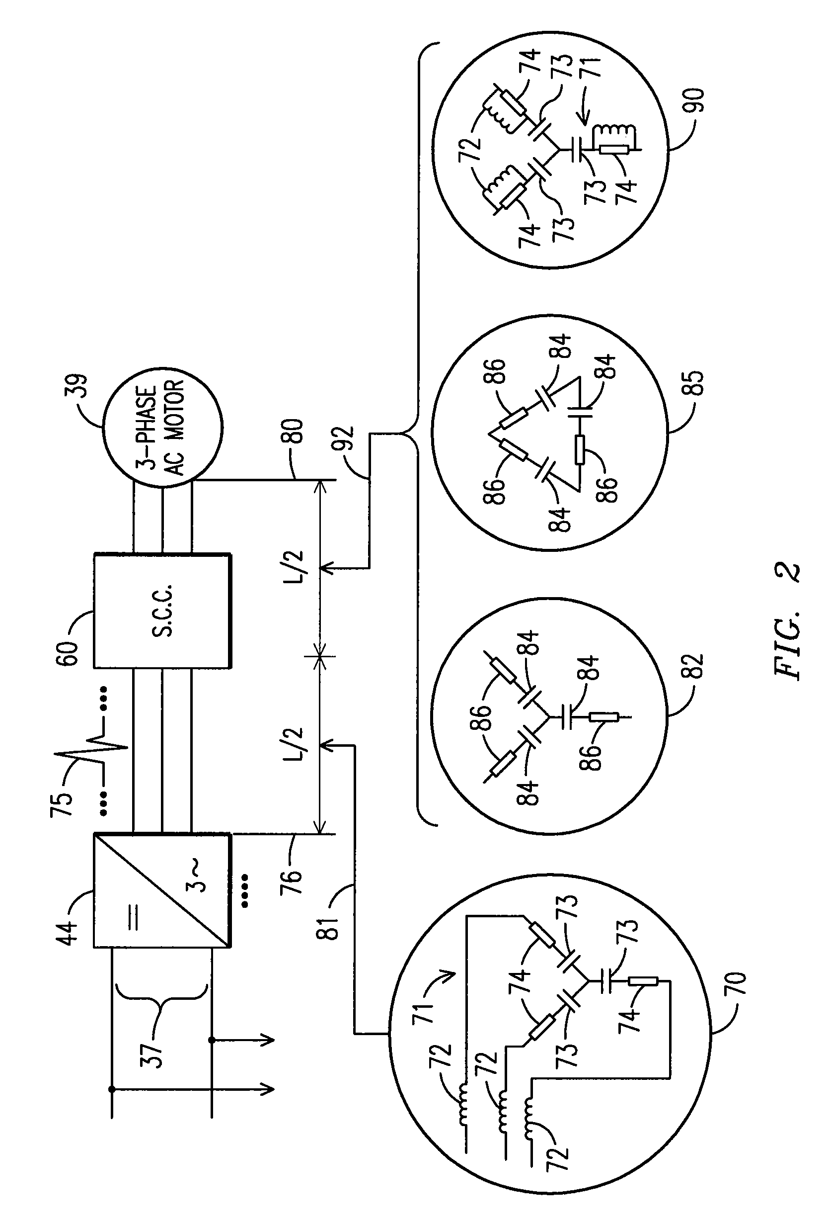
[0006]Further aspects of the present invention provide a method for arranging and operating a powered system. The method allows coupling a power bus to receive electrical power from a power source (e.g., an alternator). The method further allows coupling a traction system to the power bus. The traction system includes at least one electromotive machine having a first type of stator winding configured to provide a level of protection relative to voltage spikes expected at the traction stator under a first voltage level appropriate for the traction system. Auxiliary equipment is coupled to the power bus. The auxiliary equipment includes at least one electromotive machine having a second type of stator winding configured to provide a level of protection relative to voltage spikes expected at the auxiliary stator under a second voltage level. The second voltage level may be lower than the first voltage level. Inverter circuitry is coupled to drive the auxiliary equipment. The power bus may be operated at the first voltage level. Power from the inverter to the auxiliary equipment may be conditioned to attenuate voltage spikes produced by the inverter circuitry and / or interconnecting cables. The voltage spike attenuation is sufficient to protect the auxiliary stator notwithstanding of operating the power bus at the first voltage level.

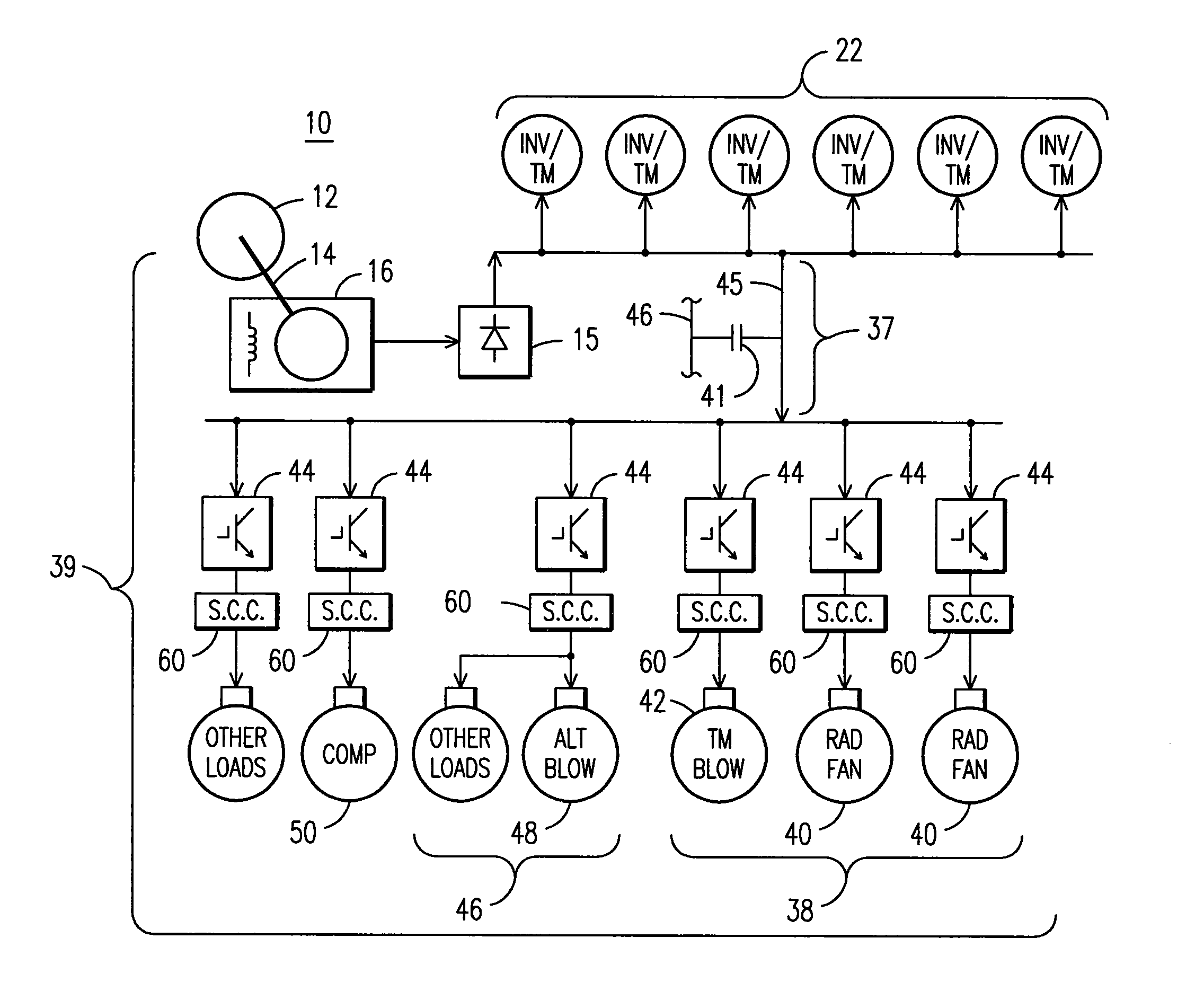
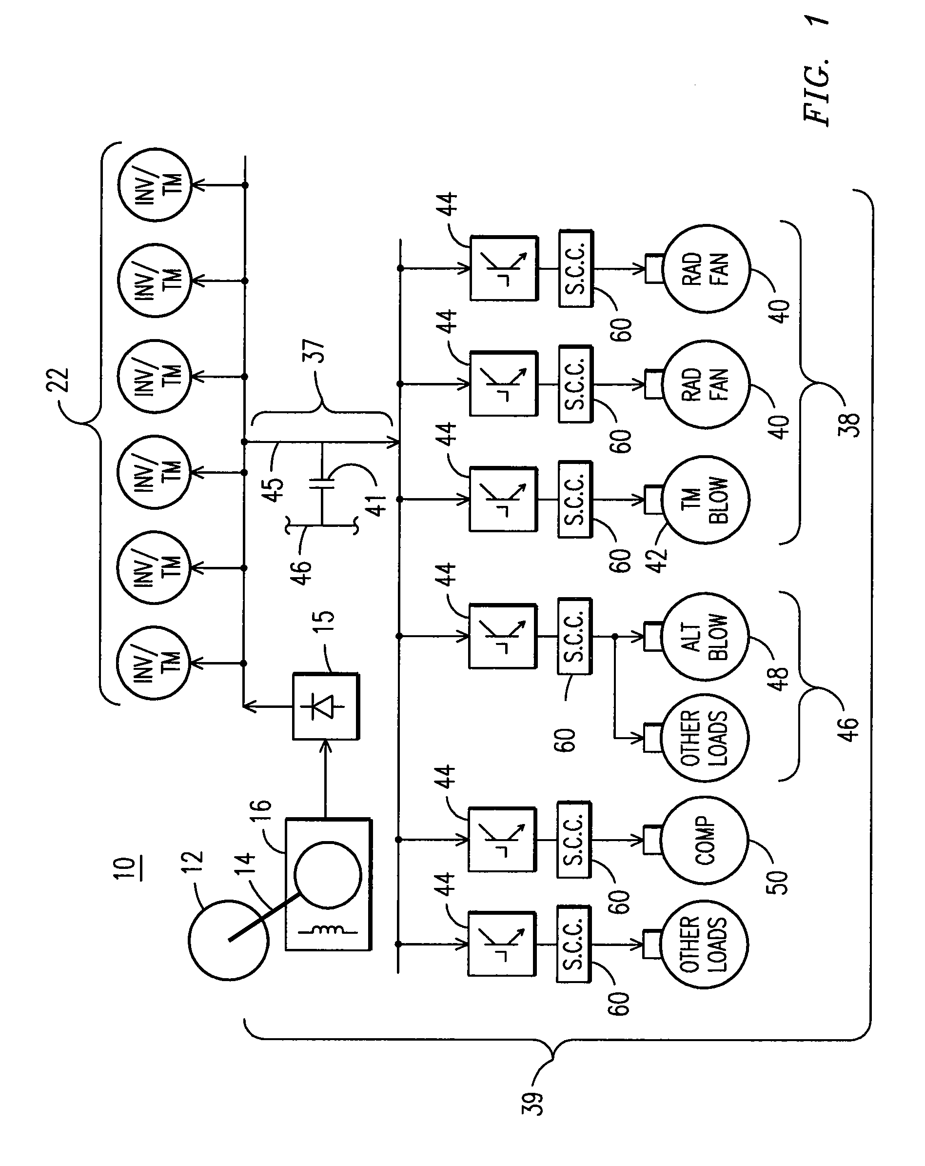
Problems solved by technology

Such spikes may repetitively (e.g., on every turn-on and turn-off) result from the switching operation of inverter drive circuitry, such as high-speed power switches (e.g., insulated gate bipolar transistor (IGBT) switches and the like) coupled to drive the equipment.

Method used


Image

  • Power system and method for driving an electromotive traction system and auxiliary equipment through a common power bus
  • Power system and method for driving an electromotive traction system and auxiliary equipment through a common power bus
  • Power system and method for driving an electromotive traction system and auxiliary equipment through a common power bus

Examples


Embodiment Construction

[0012]Aspects of the present invention may be utilized in power systems, such as may be used for driving an electromotive traction system and auxiliary equipment through a common power bus. Example vehicular applications of the power system may be in locomotives, marine vessels, off-highway vehicles (as may be equipped with rubber tires, such as mining vehicles, agricultural vehicles) and transit vehicles. For purpose of illustration, aspects of the invention are described herein as it may be applied to a locomotive.

[0013]FIG. 1 is a block diagram schematic of an example embodiment of a power system 10 in accordance with aspects of the present invention. In the embodiment depicted in FIG. 1, one or more traction motors (INV / TM) 22 and auxiliary equipment 39 may be connected to a power source, such as a main alternator 16, via a rectifier 15 that provides power to a common power bus 37. For example, the rectifier 15 may be configured for converting the AC power generated by the main ...


PUM


Abstract

Power system and method for providing electrical power are provided. The system includes a traction system and auxiliary equipment coupled to a power bus. The traction system includes one or more electromotive machines having a first type of stator winding that provides protection relative to voltage spikes expected at the traction stator under a first voltage level appropriate for the traction system. The auxiliary equipment includes one or more electromotive machines having a second type of stator winding that provides protection relative to spikes expected at the auxiliary stator under a second voltage level lower than the first voltage level. Inverter circuitry is coupled to drive the auxiliary equipment, and signal-conditioning circuitry is provided to attenuate voltage spikes produced by the inverter circuitry. The power bus is operated at the first voltage level, and the voltage spike attenuation is sufficient to protect the auxiliary stator.

Description

FIELD OF THE INVENTION[0001]The present invention is generally related to power systems, and, more particularly, to a power system for driving an electromotive traction system and auxiliary equipment.BACKGROUND OF THE INVENTION[0002]A diesel-electric locomotive typically includes a diesel engine coupled to drive a main alternator and one or more auxiliary alternators. The main alternator is coupled to power one or more traction motors, and the auxiliary alternators are coupled to power locomotive auxiliary electrical equipment, such as radiator fan motors, traction motor blowers, alternator blowers, air compressors, etc.[0003]The auxiliary equipment has generally been operated at a different voltage than the operating voltage of the traction motors. For example, the traction motors may be typically operated at a relatively higher voltage, while the auxiliary equipment may be operated at a relatively lower voltage. The lower voltage operation may allow for the use of auxiliary equipm...

Claims


Application Information

Patent Timeline
Patent Type & Authority Patents(United States)
IPC IPC(8): G05F3/06
CPCB60L1/003B60L9/005H03H1/0007B60L2200/26B60L2270/147
Inventor GUPTA, SUDHIR KUMARKUMAR, AJITH KUTTANNAIRWORDEN, BRET DWAYNEDAIGLE, JEFFREY LOUISNIKOLOV, EMILIOANNIDIS, DIMITRIOS
Owner GE GLOBAL SOURCING LLC
Learn More