Baffle for sound suppression

Inactive Publication Date: 2011-04-26
PETER CRONHELM
View PDF26 Cites 59 Cited by
  • Summary
  • Abstract
  • Description
  • Claims
  • Application Information

AI Technical Summary

Benefits of technology

[0010]The present invention discloses baffles which may be used in a discrete form with some form of separate spacer between the baffles or may be secured directly to the tube or housing of the suppressor, thereby increasing manufacturing options. In another form, the baffles may be used in a monolithic form whereby a number of baffles are machined, injection molded or cast to form a baffle stack that is of a one-piece construction. To enhance the performance, the baffles may be positioned such that one baffle is angularly rotated around the bore axis fr

Problems solved by technology

Firearms typically discharge noise and gases into the atmosphere, when fired, which may be harmful or offensive to the shooter and/or to others within the general vicinity.
While asymmetrical baffles typically produce high levels of turbulence within the sound suppressor, which aids in producing high levels of sound and flash reduction, asymmetrical baffles may result in some detrimental effects on the accuracy of the host firearm.
This does result in some inefficiencies and problems during the manufacturing process.
The problem is that with the asymmetry being on the proximal or rear

Method used


Image

  • Baffle for sound suppression
  • Baffle for sound suppression
  • Baffle for sound suppression

Examples


Embodiment Construction

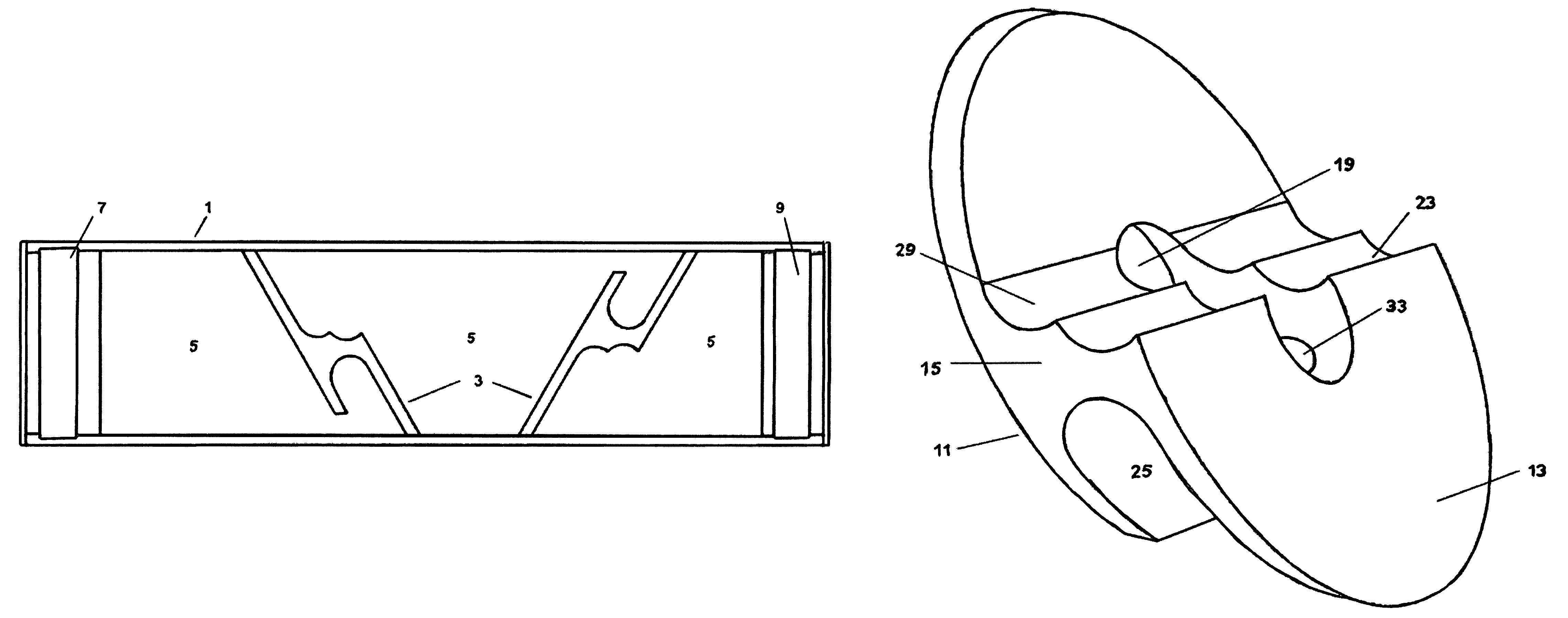
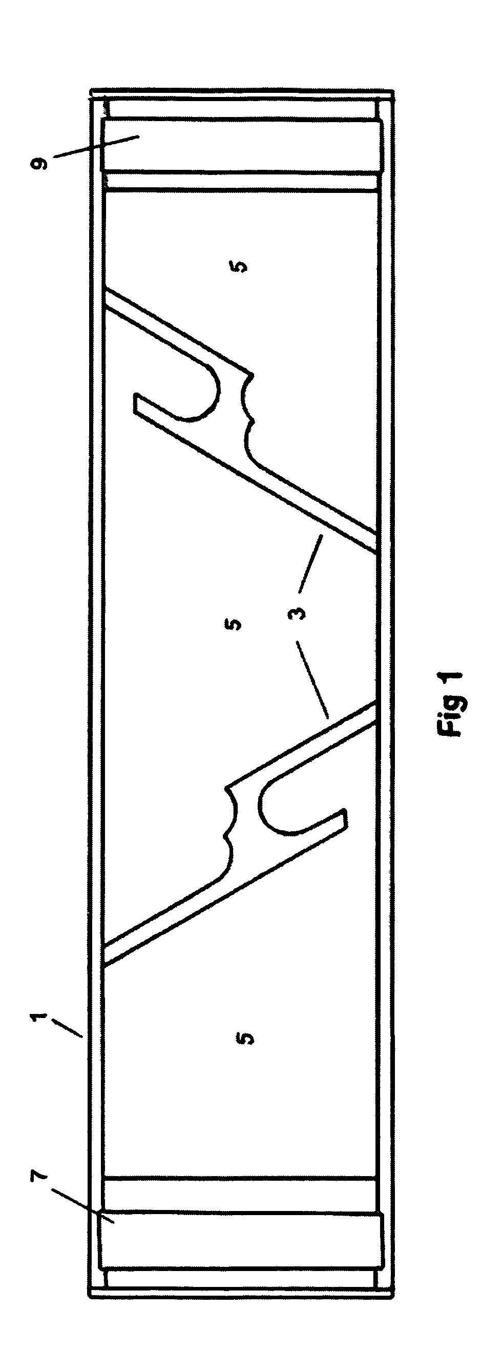
[0038]Referring now to FIG. 1 showing a perspective cross-sectional view, illustrating a sound suppressor with baffles 3 positioned along an interior of housing 1, according to an embodiment of the present invention. The sound suppressor consists of a hollow cylindrical housing 1, with spaced baffle elements 3, creating a series of expansion chambers 5, between the baffles 3. An entrance end cap 7 and an exit end cap 9 are secured to the housing 1 preferably by screw threads, by welding or other suitable securing means.

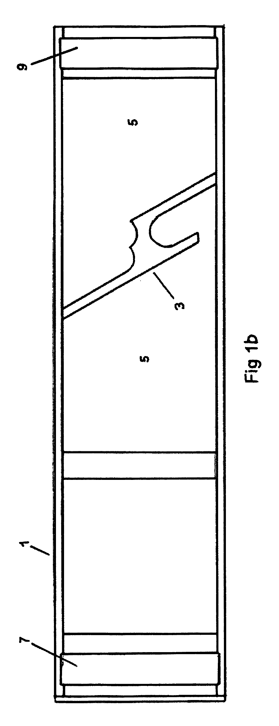
[0039]Referring now to FIG. 1b showing a perspective cross-sectional view, illustrating another embodiment of the suppressor with baffle 3 positioned along the interior of housing 1, according to the present invention. In this particular embodiment a single baffle 3 may be used to bifurcate expansion chamber(s) 5. Entrance end cap 7 and exit end cap 9 are secured to the housing 1, as also shown and discussed in FIG. 1. FIG. 1b shows a flat and symmetrical blast baffle...


PUM


Abstract

A baffle for use in a sound suppressor for a firearm utilizing proximal and distal faces with at least one joining wall positioned between the proximal and distal faces, and forming two expansion chambers between the proximal and distal faces. The joining wall has a bore hole and at least one opening in the wall itself and at least one opening from the bore hole into at least one of the expansion chambers positioned between the proximal and distal faces of the baffle. The joining wall may be either curvilinear, curvilinear stepped, planar or angled in shape. Openings are provided on the proximal face and the distal face of the baffle. At least one face of the baffle is either flat, curvilinear, curvilinear stepped, or asymmetrical to the axis of the baffle.

Description

REFERENCE TO RELATED APPLICATION[0001]This non-provisional patent application claims priority to provisional patent application No. 61 / 174,183 filed Apr. 30, 2009.BACKGROUND OF THE INVENTION[0002]1. Field of the Invention[0003]The present invention relates broadly to firearms and the reduction of noise, flash and recoil resulting from the discharge of firearms. More specifically, this invention relates to a baffle for use in sound suppressors for firearms.[0004]2. Description of the Related Art[0005]Firearms typically discharge noise and gases into the atmosphere, when fired, which may be harmful or offensive to the shooter and / or to others within the general vicinity. As a result various suppression devices have been devised in order to attempt to solve this problem. These sound suppressor devices may feature baffles that use some form of asymmetry while others may feature the use of baffles that are basically symmetrical. While asymmetrical baffles typically produce high levels of...

Claims


Application Information

Patent Timeline
IPC IPC(8): F41A21/30F41A21/36F41A21/34F41A21/32
CPCF41A21/30
Inventor CRONHELM, PETER WILLIAM
Owner PETER CRONHELM
Why Eureka
Try Eureka