
Multi-phase clock system

a clock system and multi-phase technology, applied in the field of multi-phase clock systems, can solve the problems of limiting factors, affecting the accuracy of the system, so as to achieve the effect of reducing power dissipation

Active Publication Date: 2011-05-03
NXP BV
View PDF18 Cites 25 Cited by
  • Summary
  • Abstract
  • Description
  • Claims
  • Application Information

AI Technical Summary

Benefits of technology

This approach allows for accurate de-skewing of clock signals across multiple phases, enhancing the system's ability to operate at high speeds and supporting a wider range of clock phases, including those not limited to powers of two, while reducing power dissipation and improving phase accuracy.

Problems solved by technology

This technique entails the use of several parallel data processing paths, each with limited speed.
The accuracy of the system is limited by the time accuracy of the multi-phase clock.
In particular, differences between the actual and ideal timing of a clock edge (skew) is a limiting factor.
Skew may be caused by mismatch in the multi-phase oscillator, but it may also be caused by layout asymmetry, since it is non-trivial to generate a perfectly symmetrical layout with identical delays for all paths in an interleaved system.
Although the phase accuracy of this method is acceptable, it is a “power-hungry” approach, requiring many high-speed dividers and retiming flip-flops.
Moreover, at very high frequencies, it may not be possible to generate the required HF signal at all.
However, this approach is limited by the accuracy by which a large number of phases can be produced, since some timing errors in the ring will accumulate.
A disadvantage of the known multi-phase clock system is that it is not suitable for high frequencies.
The measurement of time intervals between the individual clock phases becomes increasingly difficult at higher frequencies and also becomes relatively less accurate.
As a consequence, the known circuit has a maximum operational clock frequency that is limited by the accuracy of the time interval measurement.

Method used


Image

  • Multi-phase clock system
  • Multi-phase clock system
  • Multi-phase clock system

Examples


Embodiment Construction

[0051]It should be noted that the above-mentioned embodiments illustrate rather than limit the invention, and that those skilled in the art will be able to design many alternative embodiments without departing from the scope of the appended claims. In the claims, any reference signs placed between parentheses shall not be construed as limiting the claim. Use of the verb “comprise” and its conjugations does not exclude the presence of elements or steps other than those stated in a claim. The article “a” or “an” preceding an element does not exclude the presence of a plurality of such elements. The invention may be implemented by means of hardware comprising several distinct elements, and by means of a suitably programmed computer. In the device claim enumerating several means, several of these means may be embodied by one and the same item of hardware. The mere fact that certain measures are recited in mutually different dependent claims does not indicate that a combination of these ...


PUM


Abstract

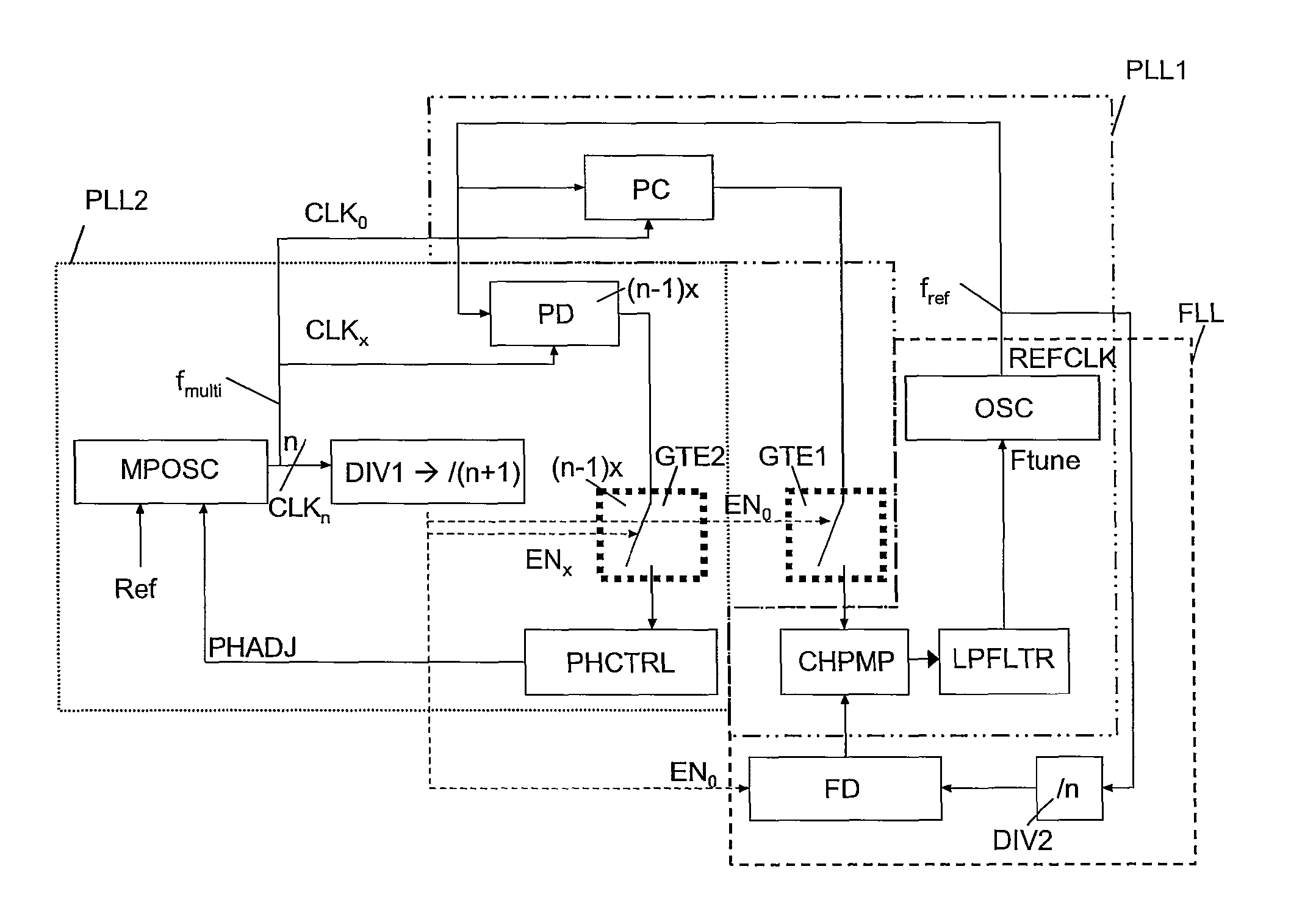
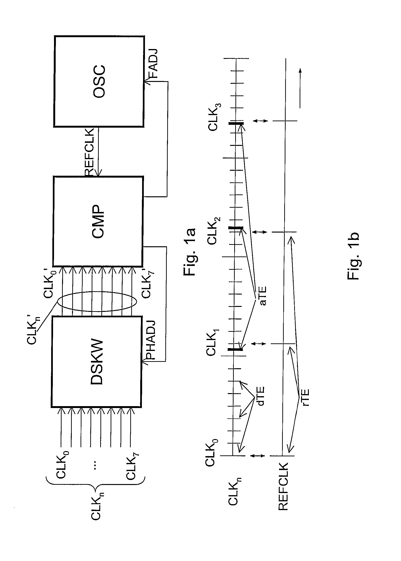
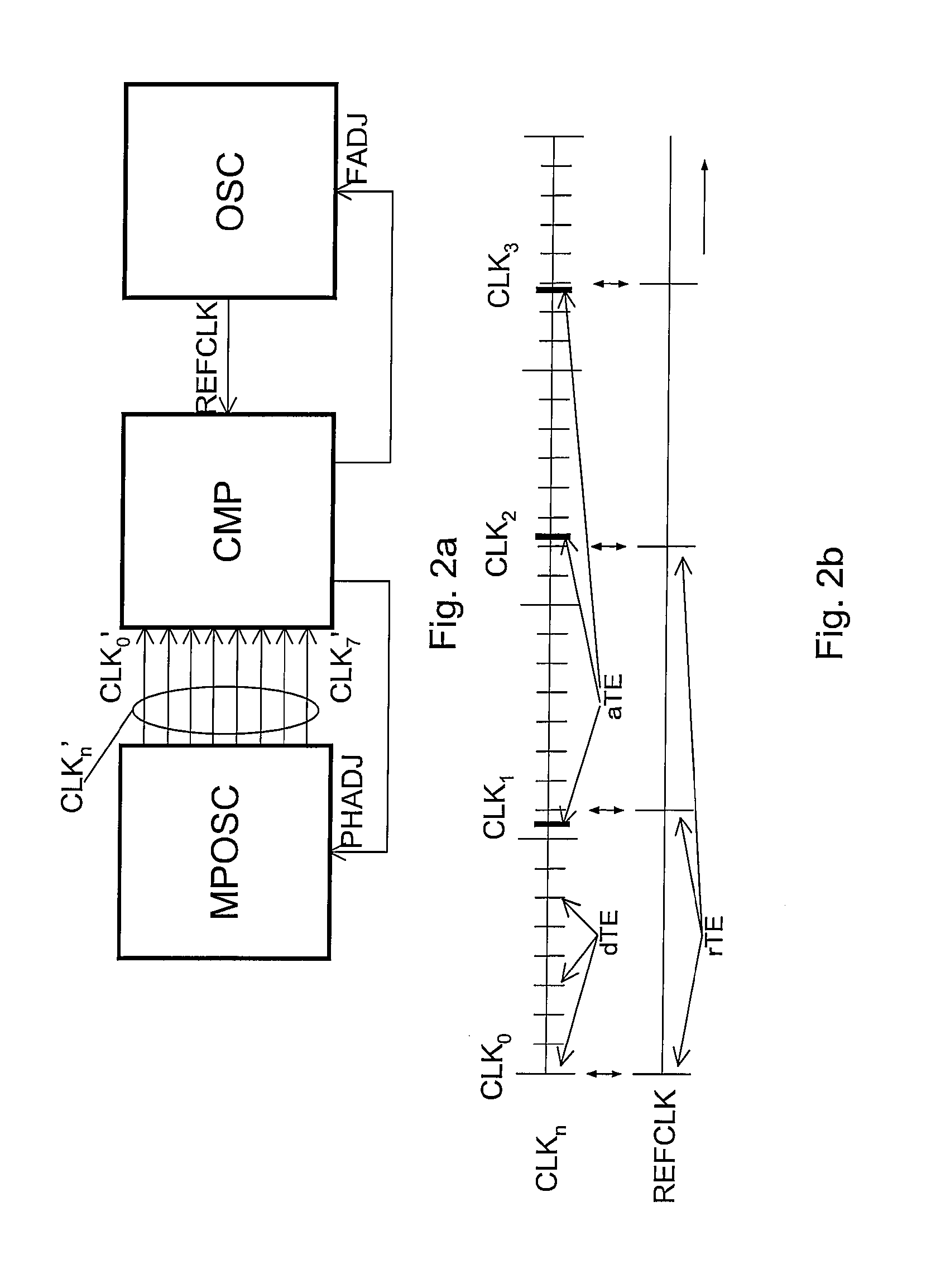
The invention relates to multi-phase clock system for receiving a plurality of clock signals (CLKo-n) comprising actual time events (aTE) defining different clock phases, the clock signals all having a same clock frequency but different clock phases, the system further arranged for receiving a reference clock signal (REFCLK) for providing reference time events (rTE) for the plurality of clock signals (CLKo-n), the reference clock signal (REFCLK) having a reference frequency different from the clock frequency, the reference frequency being selected such that each one of the subsequent reference time events (rTE) coincides with a desired time event (dTE) for a single one of the plurality of clock signals (CLKo-n).

Description

FIELD OF THE INVENTION[0001]The invention relates to a multi-phase clock system for receiving a plurality of clock signals comprising actual time events, the clock signals all having a same clock frequency but different clock phases. The invention further relates to a time-interleaved system comprising a multi-phase clock system, and to a method of receiving multi-phase clocks.BACKGROUND OF THE INVENTION[0002]Multi-phase clock systems are known, especially in time-interleaved applications. Time-interleaving is a technique which finds wide application in circuit design, for example, in Analog-to-Digital Converters (ADC's) and clock and data recovery (CDR) circuits. This technique entails the use of several parallel data processing paths, each with limited speed.[0003]In essence, interleaving means that chip area is spent in return for speed of operation. Where accurate and fast operation is required, interleaving allows the combination of accurate but slow paths into a system that be...

Claims


Application Information

Patent Timeline
Patent Type & Authority Patents(United States)
IPC IPC(8): H03L7/06
CPCH03L7/07H03L7/087H03L7/0812H03L7/10
Inventor VAN DER WEL, ARNOUD P.DEN BESTEN, GERRIT W.VAN TUIJL, ADRIANUS J.
Owner NXP BV
Learn More