Mixer with high output power accuracy and low local oscillator leakage

a technology of local oscillator and output power, applied in the direction of transmission, automatic frequency control, substation equipment, etc., can solve the problems of low output power accuracy, low leakage rate, and insufficient accuracy of output power steps, so as to avoid local oscillator signal leakage problems, improve output power level and step size accuracy and repeatability, the effect of identical layou

Active Publication Date: 2011-05-10
QUALCOMM INC
View PDF35 Cites 28 Cited by
  • Summary
  • Abstract
  • Description
  • Claims
  • Application Information

AI Technical Summary

Benefits of technology

[0014]The outputs of the MFDPs are coupled together so that the combined output power of the second signal (for example, RFOUT) is the combined power of the output signals of the various MFDPs. (In one example, the power of a signal is determined by multiplying the RMS voltage by the RMS current of the signal.) By controlling the number of MFDPs that are enabled, the output power of the second signal is controlled to have an output power that is a selected one of a plurality of discrete output power values. The discrete output power values may be referred to as output power “steps” or “levels”. Because the MFDPs are substantially identical circuits and all have substantially identical layouts, accuracy and repeatability of the output power levels and step size are improved. Because the power of the composite local oscillator signal within the novel mixer circuit is automatically changed in proportion to the number of MFDPs enabled, local oscillator signal leakage problems are avoided. The power of local oscillator signal leakage scales with the power of the desired second signal.

Problems solved by technology

In reality, however, there may be somewhat complex high frequency parasitic effects due to differences in the physical structures that make up the various mixers and due to interactions between adjacent physical structures.
Accordingly, the enabling and disabling of mixers whose sizes are binary weighted does not always result in adequate accuracy of the power of the output power steps.
This is undesirable.
Moreover, there is leakage through mixers that are not enabled, so the amount of leakage does not track well with the output power supplied by the mixers.
In the circuit topology of FIG. 3, however, the reduction in local oscillator leakage may not track with the reduction in output power of the desired output signal 18 in a suitable manner.

Method used


Image

  • Mixer with high output power accuracy and low local oscillator leakage
  • Mixer with high output power accuracy and low local oscillator leakage
  • Mixer with high output power accuracy and low local oscillator leakage

Examples


Embodiment Construction

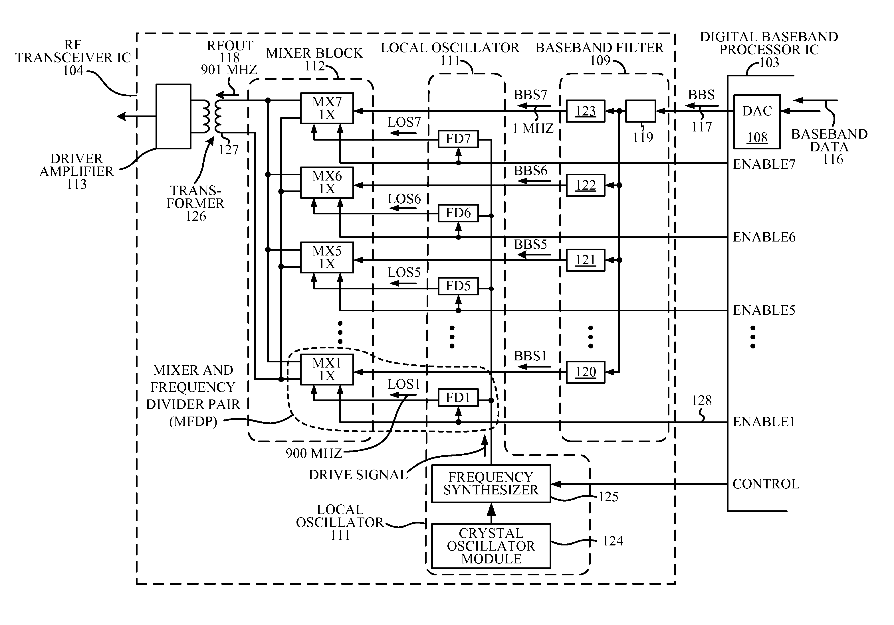
[0026]FIG. 4 is a very simplified high level block diagram of circuitry of one particular type of cellular telephone 101 in accordance with one novel aspect. In this example, cellular telephone 101 is a 3G cellular telephone that uses the WCDMA cellular telephone communication protocol. Cellular telephone 101 includes an antenna 102, several discrete components, and several integrated circuits including two integrated circuits 103 and 104. Integrated circuit 103 is called a digital baseband integrated circuit or a baseband processor integrated circuit. Integrated circuit 103 includes primarily digital circuitry and includes a digital processor. Integrated circuit 104 is called a radio frequency (RF) transceiver integrated circuit. RF transceiver integrated circuit 104 includes primarily analog circuitry. RF transceiver integrated circuit 104 is called a “transceiver” because it includes a transmitter as well as a receiver. The receiver includes a local oscillator (LO) 106 and circui...


PUM


Abstract

A circuit receives a first signal (for example, a baseband signal) and mixes it with a local oscillator (LO) signal, and outputs a second signal (for example, an RFOUT signal). The circuit includes multiple identical Mixer and Frequency Divider Pair (MFDP) circuits. Each MFDP can be enabled separately. Each MFDP includes a mixer and a frequency divider that provides the mixer with a local version of the LO signal. The MFDP outputs are coupled together so that the output power of the second signal (RFOUT) is the combined output powers of the various MFDPs. By controlling the number of enabled MFDPs, the output power of the second signal is controlled. Because the MFDPs all have identical layouts, accuracy of output power step size is improved. Because LO signal power within the circuit automatically changes in proportion to the number of enabled MFDPs, local oscillator leakage problems are avoided.

Description

BACKGROUND INFORMATION[0001]1. Technical Field[0002]The disclosed embodiments relate to local oscillators and mixers.[0003]2. Background Information[0004]FIG. 1 (Prior Art) is a very simplified high level block diagram of circuitry of a cellular telephone 1. Cellular telephone 1 includes an antenna 2, several discrete components, and several integrated circuits including a radio frequency (RF) transceiver integrated circuit 3 and a digital baseband integrated circuit 4. Digital baseband integrated circuit 4 includes primarily digital circuitry and includes a digital processor. RF transceiver integrated circuit 3 includes primarily analog circuitry. RF transceiver integrated circuit 3 is called a “transceiver” because it includes a transmitter as well as a receiver.[0005]FIG. 2 (Prior Art) is a more detailed diagram of the RF transceiver integrated circuit 3 of FIG. 1. The receiver includes what is called a “receive chain”5 as well as a local oscillator (LO) 6. When the cellular tele...

Claims


Application Information

Patent Timeline
Patent Type & Authority Patents(United States)
IPC IPC(8): H04B7/00
CPCH03D7/165H04B1/0483H04B2001/0491H04B2001/0416
Inventor ANIRUDDHAN, SANKARANSUN, BOJAYARAMAN, ARUNSAHOTA, GURKANWAL SINGH
Owner QUALCOMM INC
Why Eureka
Try Eureka