Microprobe array structure and method for manufacturing the same

a microprobe array and array technology, applied in the field of microprobe array structure, can solve the problem that the conventional microprobe array cannot be firmly stabilized in the skin tissue, and overcome the drawback of the conventional microprobe array

Inactive Publication Date: 2011-05-10
NAT CHIAO TUNG UNIV
View PDF7 Cites 45 Cited by
  • Summary
  • Abstract
  • Description
  • Claims
  • Application Information

AI Technical Summary

Benefits of technology

[0008]To achieve these and other advantages and in order to overcome the disadvantages of the conventional method in accordance with the purposes of the invention as embodied and broadly described herein, the present invention provides a microprobe array structure with self-stabilization capability. The microprobe array structure can be used as a stimulus or a sensing electrode in biopotential measurement systems to measure various biopotential signals. Moreover, the drawback that the conventional microprobe array cannot be firmly stabilized in the skin tissue can be overcome.
[0009]Because the microprobe has the tip portion 34 and can puncture the Stratum Corneum 50 to get into the Stratum Germinativum 52, better electric conductivity can be obtained. Moreover, because the microprobe is self-stabilizing within the Stratum Germinativum, the biopotential measurements can be better made and / or maintained. Therefore, the microprobe won't easily loosen up in the skin tissue, and has a self-stabilization capability to overcome the drawback that the conventional microprobe array cannot be firmly stabilized in the skin tissue. Further, because the microprobe exploits the skins natural elastic / contractile property to self-stabilize; the microprobe does not anchor itself into tissue causing potential damage to the adjacent cells as with barbed spikes / probes.
[0010]Another object of the present invention is to provide a method for manufacturing a microprobe array structure. The method has a simple manufacturing process that can be easily carried out. Therefore, the manufactured microprobe array has a low cost and can be mass produced.

Problems solved by technology

Moreover, the drawback that the conventional microprobe array cannot be firmly stabilized in the skin tissue can be overcome.

Method used


Image

  • Microprobe array structure and method for manufacturing the same
  • Microprobe array structure and method for manufacturing the same
  • Microprobe array structure and method for manufacturing the same

Examples


Embodiment Construction

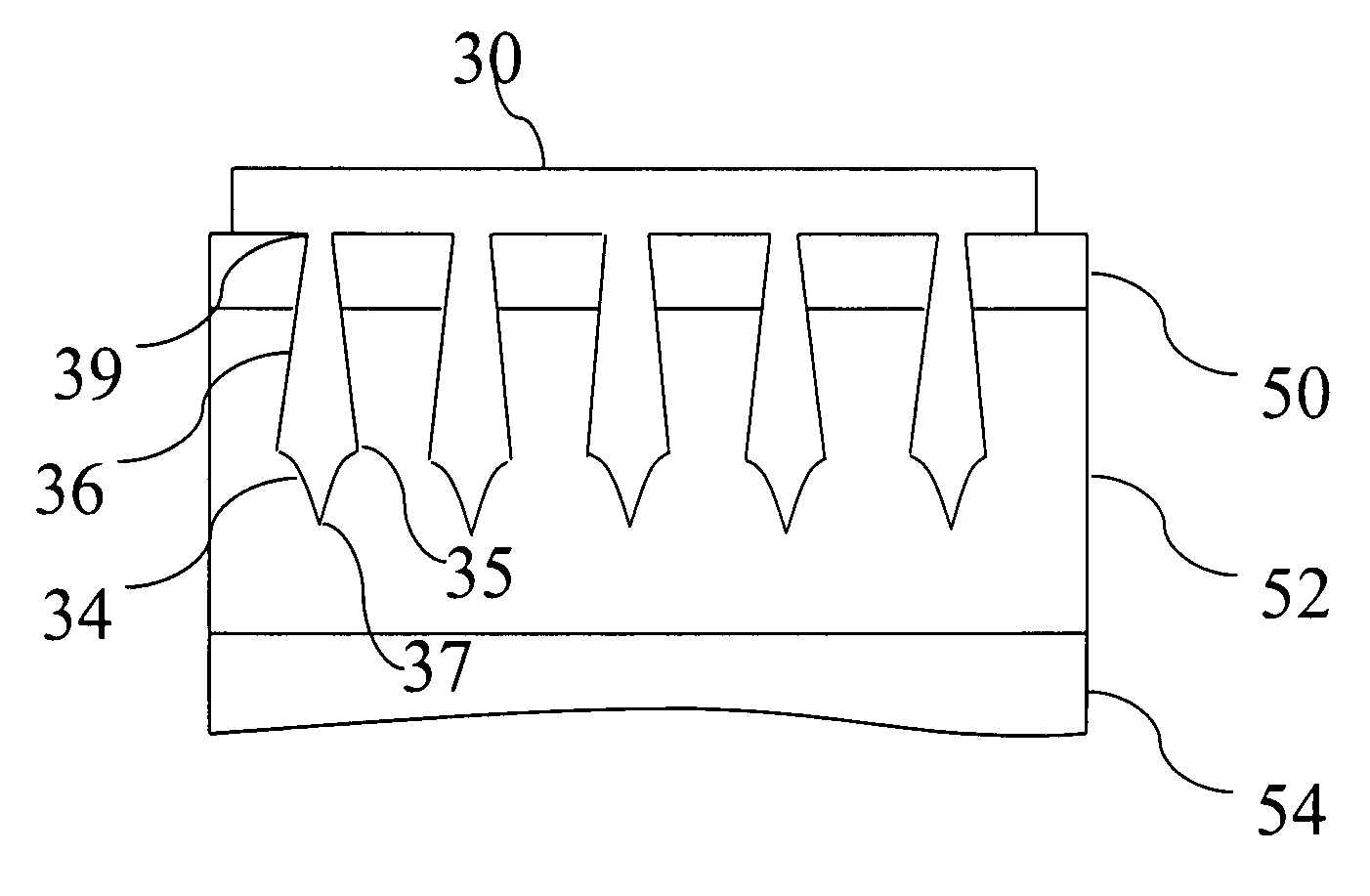
[0022]It is the object of the present invention to provide a self stabilizing electrode suitable for mounting on the skin of a patient and which provides an improved signal to noise ratio to the bioelectrical signal obtained by the electrode. The present invention proposes an improved microprobe structure with inherent self-stabilizing features which can be used to measure various biopotential signals as electrocardiography (ECG / EKG) signals, electroencephalography (EEG) signals, electrical impedance tomography (EIT) signals, electromyography (EMG) signals and electro-oculography (EOG) signals. As used herein, the terms “biopotential”, “bioelectrical” and “biosignal” are used interchangeably and generally refer to the information received from the invention electrodes.

[0023]The microprobe electrode of the present invention reduces skin impedance and artifacts by increasing signal quality through use of microprobes to penetrate the Stratum Corneum into viable epidermis. In addition t...


PUM


Abstract

A microprobe array structure with self-stabilization capability and a method for manufacturing the same are proposed. The microprobe array structure is used to sense various biopotential signals, and is characterized in that the etching parameters are controlled during etching to manufacture a microprobe structure with a reduced bottom cross section so that the microprobe can be firmly stabilized in the skin tissue. Moreover, a conducting layer is formed on the microprobe to sense signals. A design of electric isolation between microprobes is also proposed. The microprobe array can therefore be used for the measurement of various biopotential signals, and can also be used as a stimulus.

Description

FIELD OF THE INVENTION[0001]The present invention relates to a microprobe array structure and a method for manufacturing the same and, more particularly, to a microprobe array structure with self-stabilization capability for biopotential signals measurements, and a method for manufacturing the same.BACKGROUND OF THE INVENTION[0002]Electrodes for measuring biopotential are used extensively in modern clinical and biomedical applications. These applications encompass numerous physiological tests including electrocardiography (ECG / EKG), electroencephalography (EEG), electrical impedance tomography (EIT), electromyography (EMG) and electro-oculography (EOG). The electrodes for these types of physiological tests function as a transducer by transforming the electric potentials or biopotentials within the body into an electric voltage that can be measured by conventional measurement and recording devices.[0003]Most physiological electrodes for such applications are placed on the skin. The s...

Claims


Application Information

Patent Timeline
Patent Type & Authority Patents(United States)
IPC IPC(8): A61B5/04
CPCA61B5/0408A61B5/685A61B5/14514A61B5/0478A61B5/25A61B5/291A61B5/262A61B5/257A61B5/266
Inventor CHIOU, JIN-CHERNHUNG, CHEN-CHUNCHANG, CHIH-WEI
Owner NAT CHIAO TUNG UNIV
Why Eureka
Try Eureka